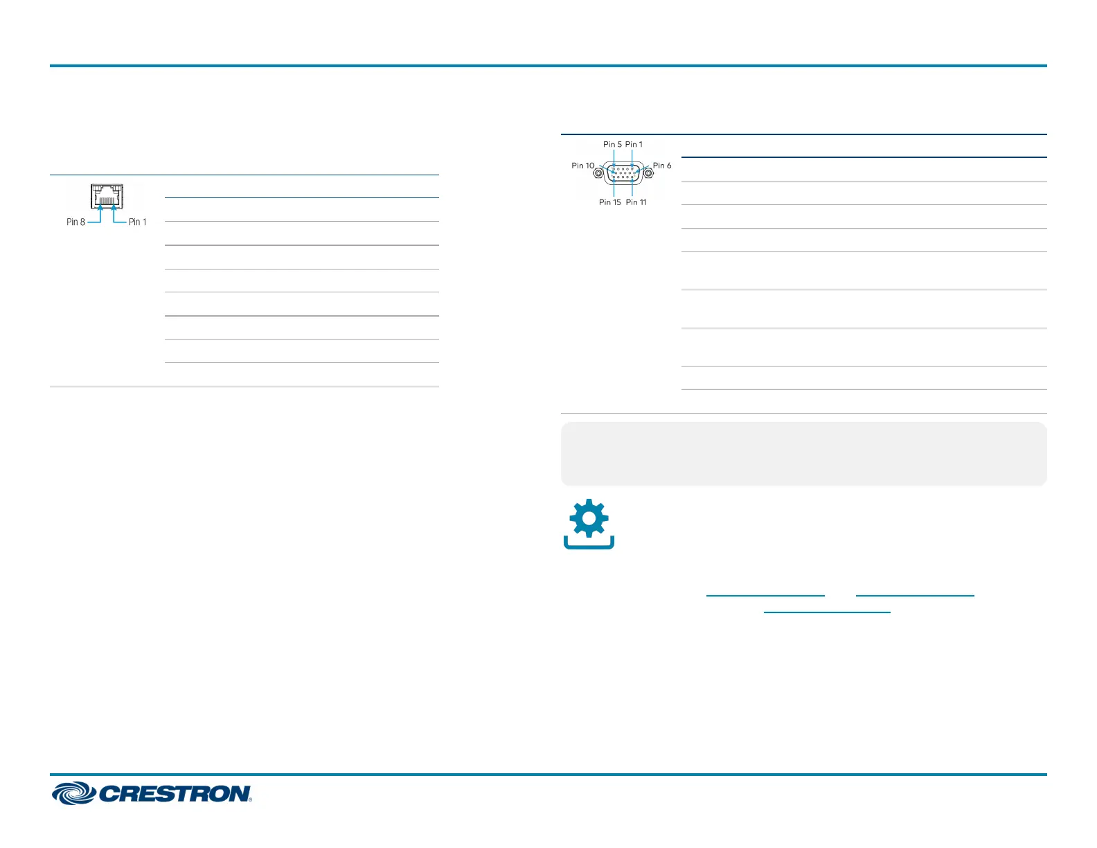
For information about DM OUT and VGA IN connector pin assignments,
refer to the following illustrations and tables.
DM OUT Wiring
Pin Number Wire Color
1 Orange/White
2 Orange
3 Green/White
4 Blue
5 Blue/White
6 Green
7 Brown/White
8 Brown
VGA IN Wiring (DM-TX-4K-302-C Only)
PinNumber RGB YPbPR S-Video Composite
1 R Pr C
2 G Y Y
3 B Pb COMP
5 GND GND GND GND
6 RED_
GND
PR_
GND
C_
GND
7 GRN_
GND
Y_
GND
Y_
GND
8 BLU_
GND
Pb_
GND
13 H
14 V
NOTE: For best video performance, ground connections should be kept
separate. Do not connect ground wires to the connector shell. The
connector shell is reserved for the cable shield.
Upgrade the Firmware
Before using the device, upgrade the firmware. The latest firmware can be
downloaded from the DM-TX-4K-202-C and DM-TX-4K-302-C product
page on the Crestron website (www.crestron.com).
4
DM-TX-4K-202-C and DM-TX-4K-302-C
QuickStart
4K DigitalMedia 8G+® Transmitters

 Loading...