Crestron AV3 & PRO3 3-Series Control Systems
Operations Guide – DOC. 7330C 3-Series Control Systems: AV3 & PRO3
9
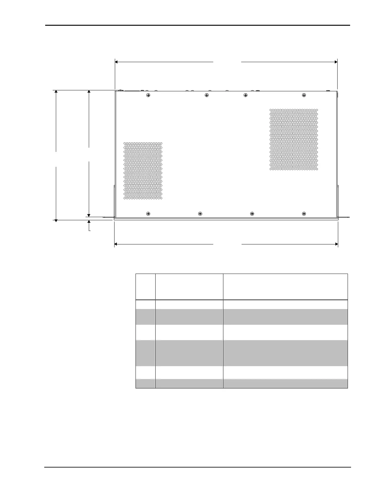
AV3 & PRO3 Overall Dimensions (Top View, PRO3 shown)
17.16 in
(436 mm)
9.78 in
(249 mm)
10.06 in
(256 mm)
0.25 in
(7 mm)
17.28 in
(439 mm)
Connectors, Controls & Indicators
# CONNECTORS
1
,
CONTROLS &
INDICATORS
DESCRIPTION
1 PWR LED (1) Green LED, indicates that unit is powered
2 NET LED (1) Amber LED, indicates communication
with the Cresnet system
3 MSG LED (1) Red LED, indicates control system has
generated an error message
4 CNPS FAULT
(LED and Button)
(1) Red LED and (1) push button;
LED indicates an excessive Cresnet load was
detected at NET port;
Push button resets the fault indication
5 NAV PAD
2
(1) 5-way navigation pad for menu navigation
and parameter adjustment
6 HOME Button
(1) Push button, returns to the home menu
(Continued on following page)