3-Series Control Systems Crestron AV3 & PRO3
10
3-Series Control Systems: AV3 & PRO3 Operations Guide – DOC. 7330C
Connectors, Controls & Indicators (Continued)
# CONNECTORS
1
,
CONTROLS &
INDICATORS
DESCRIPTION
7 Reset Buttons
HW-R – Initiates system hardware and user
program reset
SW-R – Restarts the program when pressed
alone while the system is running
Restarts without loading user programs when
both HW-R and SW-R buttons are pressed
together, HW-R is released, and SW-R
button is held for an additional 30 seconds
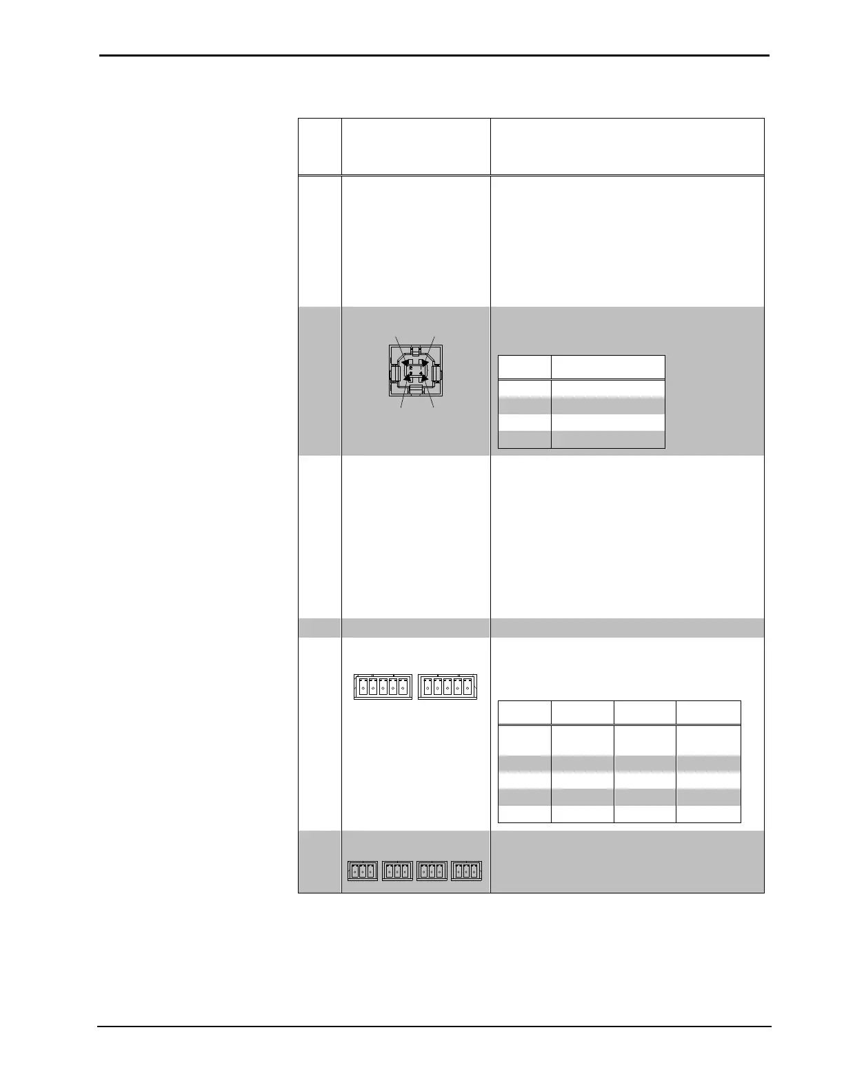
8 COMPUTER
(1) USB Type B female;
USB 2.0 computer console port (6 ft cable
included)
PIN DESCRIPTION
1 +5 Vdc
2 Data -
3 Data +
4 Ground
9 SLOT (1 – 3) LEDS
3
(3) Green LEDs;
Off indicates card is not installed or not
responding;
On indicates card is installed and is
communicating with AV3 or PRO3 processor
as programmed in Crestron Studio™ or
SIMPL Windows;
Blinking indicates card is installed, but is
either not communicating with processor or
not included in AV3/PRO3 Crestron Studio or
SIMPL Windows program
10 BACK Button
2
(1) push button, steps menu back one level
11 COM (1 – 2)
4
G
TX
RX
RTS
CTS
G
TX
RX
RTS
CTS
G
TX-
RX+
TX+
RX-
G
TX-
RX+
TX+
RX-
(2) 5-pin 3.5 mm detachable terminal blocks;
Bidirectional RS-232/422/485 ports;
Up to 115.2 kBd;
Hardware and software handshaking support
PIN # RS-232 RS-422 RS-485
1 GND GND
GND
5
2 TX TX- TX-/RX-
3 RX RX+ Not used
4 RTS TX+ TX+/RX+
5 CTS RX- Not used
12 COM (3 – 6)
4
(4) 3-pin 3.5 mm detachable terminal blocks;
Bidirectional RS-232 ports;
Up to 115.2 kBd;
Software handshaking support
(Continued on following page)