Crestron AV3 & PRO3 3-Series Control Systems
Operations Guide – DOC. 7330C 3-Series Control Systems: AV3 & PRO3
11
Connectors, Controls & Indicators (Continued)
# CONNECTORS
1
,
CONTROLS &
INDICATORS
DESCRIPTION
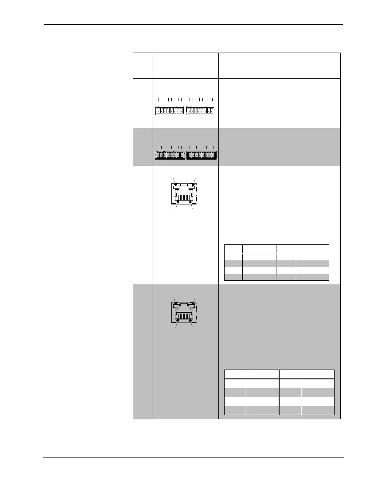
13 IR - SERIAL
OUTPUT (1 – 8)
6
1 2 3 4 5 6 7 8
S G S G S G S G S G S G S G S G
(2) 8-pin 3.5 mm detachable terminal blocks
comprising (8) IR/Serial output ports;
IR output up to 1.2 MHz;
1-way serial TTL/RS-232 (0-5 volts) up to
115.2 kBd;
Individual signal generator per port, allowing
simultaneous firing of all ports
14 RELAY OUTPUT
(1 – 8)
1 2 3 4 5 6 7 8
1A 30VAC/DC MAX
(2) 8-pin 3.5 mm detachable terminal blocks
comprising (8) normally open, isolated
relays;
Rated 1 amp, 30 volts ac/dc;
MOV arc suppression across contacts
15 LAN
4
(1) 8-wire RJ-45 jack
10/100/1000Base-T Ethernet port
Left bicolor LED indicates Ethernet link status
and connection speed
Amber: Link – 1 Gbps
Green: Link – 100 Mbps
Off: No link or Link – 10 Mbps
Right amber LED indicates Ethernet activity
Flashing: Activity – Flash rate
depends on amount of activity
Off: No Activity
Connects to the customer’s LAN
PIN SIGNAL PIN SIGNAL
1 BI_DA + 5 BI_DC -
2 BI_DA- - 6 BI_DB -
4 BI_DC + 8 BI_DD -
16 CONTROL SUBNET
4
(1) 8-wire RJ-45 jack
10/100/1000Base-T Ethernet port
Provides a dedicated local network for
Crestron devices
Left bicolor LED indicates link status and
speed
Amber: Link – 1 Gbps
Green: Link – 100 Mbps
Off: No link or Link – 10 Mbps
Right amber LED indicates Ethernet activity
Flashing: Activity – Flash rate
depends on amount of activity
Off: No Activity
PIN SIGNAL PIN SIGNAL
1 BI_DA + 5 BI_DC -
2 BI_DA- - 6 BI_DB -
3 BI_DB + 7 BI_DD +
4 BI_DC + 8 BI_DD -
(Continued on following page)