3-Series Control Systems Crestron AV3 & PRO3
12
3-Series Control Systems: AV3 & PRO3 Operations Guide – DOC. 7330C
Connectors, Controls & Indicators (Continued)
# CONNECTORS
1
,
CONTROLS &
INDICATORS
DESCRIPTION
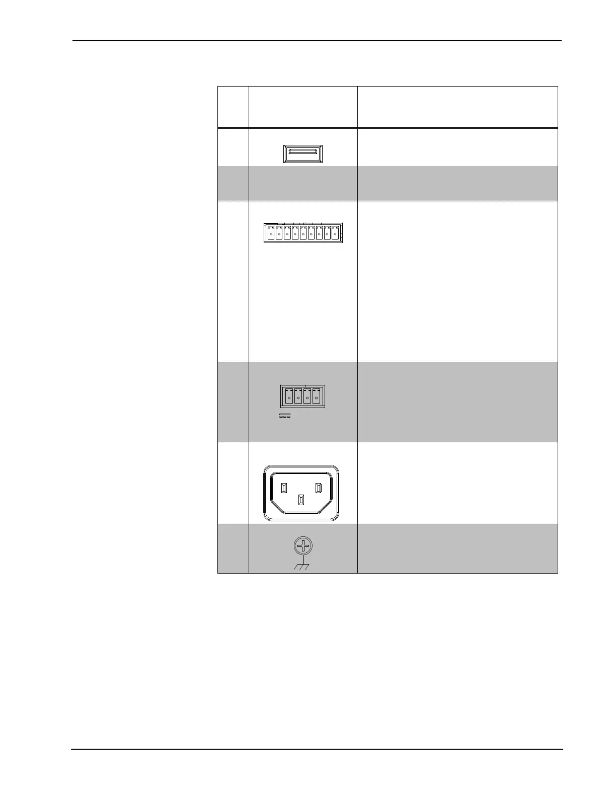
17 USB
(1) USB Type A female;
USB 2.0 port for storage devices
18 MEMORY
(1) Memory card slot;
Accepts up to 32 GB for memory expansion
(SD memory card not included)
19 I/O (1 – 8)
(1) 9-pin 3.5 mm detachable terminal block
comprising (8) “Versiport” digital input/output
or analog input ports (referenced to GND);
Digital input: Rated for 0-24 volts dc, input
impedance 20 kΩ, logic threshold
>3.125 V low/0 and <1.875 V high/1;
Digital output: 250 mA sync from maximum
24 volts dc, catch diodes for use with “real
world” loads;
Analog input: Rated for 0-10 volts dc,
protected to 24 volts dc maximum, input
impedance 21 kΩ with pull-up resistor
disabled;
Programmable 5 volts, 2 kΩ pull-up resistor
per pin
20 NET
4
(1) 4-pin 3.5 mm detachable terminal block;
Cresnet master port, outputs power to
Cresnet devices;
24: Power (24 volts dc)
Y: Data
Z: Data
G: Ground
21 100 – 240V ~2.4A
50/60 Hz
(1) IEC C14 male chassis plug, main power
input;
Mates with removable power cord, included
22 GROUND
(1) 6-32 screw, chassis ground lug
1. Interface connectors for COM 1–2, COM 3–6, I/O-SERIAL OUTPUT, RELAY OUTPUT, I/O
and NET ports are provided with the unit.
2. PRO3 only.
3. AV3 requires CAGE3 Control Card Accessory.
4. Complies with IEC 61000-4-5 Installation Class 4 surge immunity levels.
5. A ground terminal connection is recommended but not required. Ground potential difference must be
under +/-4 V.
6. Transmission levels on the infrared – serial output connectors are in the 0 to +5 Vdc range, which may
not be compatible with all RS-232 devices.