Fume Hood Monitor and Controller – User Guide 25 © 2016 CRITICAL ROOM CONTROL
Diagnostic Screen
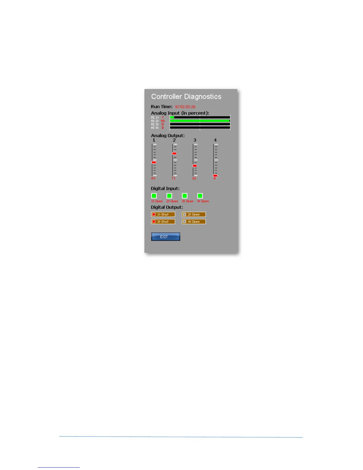
The diagnostic screen allows the installer to easily troubleshoot connections to the CRC-FHM /
FHC device. This screen visually shows the incoming signal for all analog and digital inputs, and
allows the user to set individual Analog outputs or relays. The diagnostic screen also displays total
controller run time. This utility screen bypasses control functions that influence the unit’s I/Os
(i.e. PID signal output will not be functional).
Run Time
Run time displays the total time that the unit has been powered in HOURS:
MINUTES:SECONDS:MILLISECONDS - Run time resets on power loss.
Analog Input
Displays associated Analog In (AIN1 thru 4) in bar form based on physical jumper inputs.
IMPORTANT NOTE: our unit reads the full range of a mA signal – so receiving 10mA for a 4-20mA
signal will result in reading of 50%.
Analog Output
Move the slider(s) up or down to vary the signal output. The value (in percentage of total signal
output will be displayed at the bottom of the slider in red.
Digital Input
Indicates the status of Digital Inputs (DI-1 thru 4).
Digital Output
User can open or close a relay by touching any of the Digital Output buttons.
 Loading...