t) If you are using the unit on a carpet, make sure
that the air supply to the ventilation holes is suffi-
cient.
u) Only one person may use the unit at a time.
v) Protect the vibration plate against moisture and
water, and ensure that the electrical components
do not come into contact with water.
w) This device is not suitable for pregnant women
and persons with reduced physical, sensory or
mental abilities. Persons who do not have any ex-
perience with equipment such as these need an
explanation on how the machine operates and
how to use before using it for the first time.
x) It is dangerous to reach into the inside area of the
foot plate with your hand.
y) Always make sure that weight is evenly distributed
to avoid damage to the unit and the development
of noise.
3
33
3 L
LL
L
IST OF PAR
IST OF PARIST OF PAR
IST OF PARTS
TSTS
TS
Description
DescriptionDescription
Description
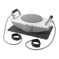
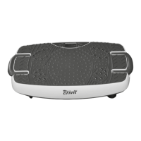
Centre section of housing
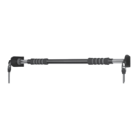
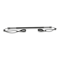
Stretch tube with handle (
Power cable with power plug
Hexagonal head bolt M8 x 25
Description
DescriptionDescription
Description
Cover for axle mounting bracket
Figure A shows the exploded assembly drawing of
your new equipment. Please note that the unit is al-
ready pre-assembled.
4
44
4 I
II
I
NSTRUCTIONS FOR USE
NSTRUCTIONS FOR USENSTRUCTIONS FOR USE
NSTRUCTIONS FOR USE
4.1
4.14.1
4.1 General instructions
General instructionsGeneral instructions
General instructions
The equipment is already fully assembled. Check that
your new equipment is complete with no parts missing
before using it for the first time. Make sure that you
have emptied the box completely. If, despite our quality
controls, a part or two are missing, please contact our
service centre using the contact details at the end.
4.2
4.24.2
4.2 Computer
ComputerComputer
Computer
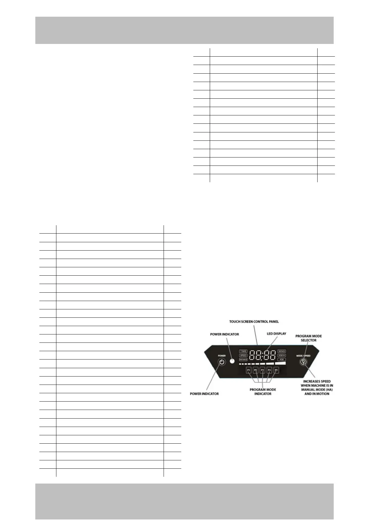
The figure above shows the Touch Screen Control Panel
on the vibration board. The LED display shows, among
other things, the time. A possibly selected training pro-
gram („Program Mode Indicator‰) is displayed below
it.