EasyManua.ls Logo

Crossfire GX1 - Connector Layout and Port Identification

Crossfire GX1
32 pages
Print Icon
To Next Page IconTo Next Page
To Previous Page IconTo Previous Page
Loading...
CrossFire GX1
Date: Apr 26, 11
Manual and reference handbook
www.crosscontrol.com
10
5.2. Connector Layout
In order to facilitate the discussion of CrossFire GX1, each I/O pin is assigned with a unique port
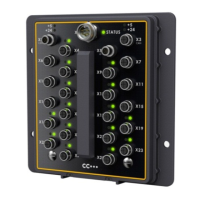
number. The ports are accessible through connectors numbered X4 to X25. The port numbering:
acts as an interface between hardware and software
allows easy mapping to the object dictionary’s index/subindex system
distinguishes the electrical independence (i.e. despite identical signal names)
identifies internal I/O so that it can be reflected in the object dictionary
X1 Power Supply Connector
Pin
Port
Default Signal
Comments
DIN 7/8
male, 5-pole
X1.1
-
+24 V Power
Supply for I/O (V
batt
)
X1.2
-
+24 V Power
X1.3
-
GND
Battery ground
X1.4
-
GND
X1.5
-
+24 V Logic
Supply for logic (V
batt
)
ID
AIN
AIN
AIN
CANout
CANout
AIN
AIN
AIN
DIO
DIO
DIO
DIO
DIO
DIOP
DIOP
DIOP
DIOP
DIOP
DIOP
DIOP
EDIO
EDIO
DIOP
Right Side
Left Side
Power