Manual and reference handbook
6. Electrical Interface Overview
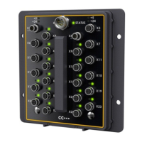
CrossFire GX1 is highly configurable. The following illustration consists of several boxes which
represent the main interfaces on CrossFire GX1. Each port is associated with a single Interface.
Each interface can have one of many functions. The arrows leading to and from the interfaces
represent I/O, power or communication busses. Many of the ports are individually configurable.
Identification Interface (ID)
Digital Inputs/Outputs (DIO)
Digital Inputs/Outputs/
PWM Outputs (DIOP)
12 Ports
(1 – 6 & 37 to 42)
Also configurable as:
6 Digital Inputs (odd
numbered ports)
+24 V Sensor Supply 1 & 2 / GND
+5 V Sensor Supply 1 & 2 / GND
Possible Node ID 1 to
16 (CANopen version
specific)
Also configurable as
4 Digital Inputs
May be individually
configured as:
2 Encoder Inputs
(default)
4 Digital Inputs
4 Digital Sinking
Outputs
1 Pulse Counter Input
May be individually
configured as:
10 Digital Outputs
(default)
10 Digital Inputs
1 Pulse Counter Input
10 Ports
(9,10,19–22, 33–36)
Configured by default
as:
16 Digital Inputs
May also be individually
configured for up to
16 Digital Outputs
16 PWM Outputs
(8 Opposing pairs)
PWM GND (Current
Sens.)
16 Ports
(27 – 32, 45, 46)
Single CAN BUS Interface
with 2 connectors
to AIN, DIO, DIOP and EDIO interfaces
X6, X10, X14,
X7, X11, X15
X4, X8, X12, X16
X9, X13, X17, X23
5 Ports - Voltages
(Ports 58 to 61, 63)
1 Port Case Temperature
(Port 62)
Monitor of
Case Temperature
3 Supply Voltages
2 5-V Ref. Voltages