Menu system overview Crowcon Gasmaster
24
Over the next few pages you will find a detailed
description of the menu system. Use figure 3.4 as
an overall guide to locate menu items.
Gasmaster has five standard menus: Faults,
Warnings, View, Actions and Supervisor. Only the
Supervisor menu allows you to configure Gasmaster.
This section contains tables that list the menu
items for each menu and the available values.
See "Using the Control Panel in Supervisor Mode"
on page 21 for instructions on how to alter set-
tings.
Note: The display only shows two lines of infor-
mation at a time. Use the Up
and Down
buttons to see additional menu items or values.
Use Continue
to select choices and Back to
exit menu.
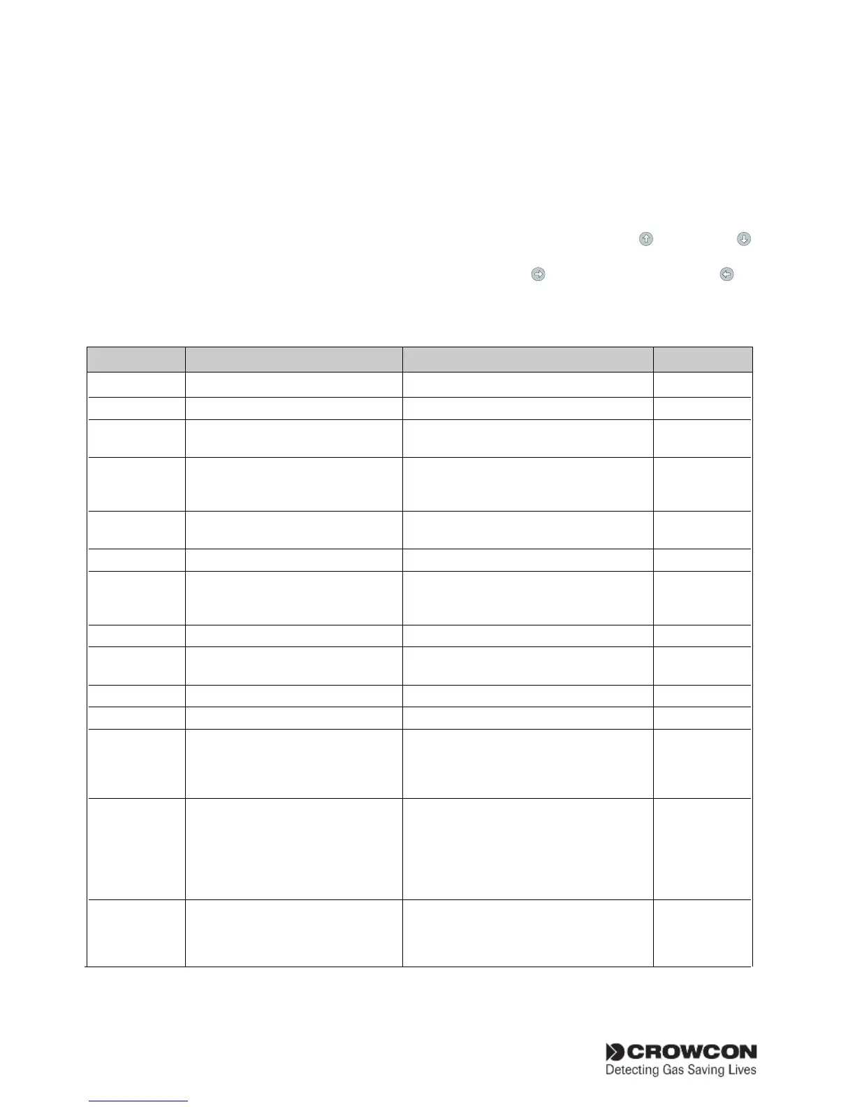
Menu system overview
Menu Item Values (as shown on display) Description Fault codes
Faults menu (lists faults present on the system)
No faults (end of list) No faults are present
Faults Measurement system failure! Fatal fault, contact Crowcon. 1 or 2
Warning - Battery low Input supply has failed and internal 4
battery supply has dropped to 22 volts.
Relay power supply fail Power rail to the relays has failed and 5
relays will no longer operate. Contact
Crowcon
Main supply fail Main supply has failed and the system 6
is running on batteries
NVM hardware fail Fatal fault, contact Crowcon. 7
Loaded default settings System has returned to standard 8
configuration settings. Re-configure
using the Supervisor menu.
Common relay fail Coil fault detected. Contact Crowcon 9, 10, 11
Chan #1 relay fail Channel relay coil fault detected. 12 to 19
Contact Crowcon.*
ESU #1 stalled! ESU sampling device has stopped.* 20 to 23
ESU #1 slow! ESU sampling device has slowed.* 24 to 27
Chan #1 over range Detector input signal is over 21.5 mA. 28 to 31
Investigate cause at detector taking
necessary precautions as high gas
levels may be present.*
Chan #1 under range Detector input signal is under 3 mA. 32 to 35
Check detector.* If the 'Interpret
2 mA' command is set to Warning
or Inhibit in the channel configuration,
this fault message will display when
the input signal drops below 1mA.
Chan #n: pellistor saver mode mV pellistor type detector has been 36-39
exposed to gas in excess of 95%LEL.
A 200-second timer will be applied,
after which the fault may be reset
* #1 denotes the channel number and therefore may read #2, #3 or #4 on Gasmaster.
The fault codes are numbered to relate to a particular channel where appropriate (e.g. fault code 19 means there is a fault
on Channel 4 Level 2 alarm relay).