Crowcon Gasmaster Menu system overview
27
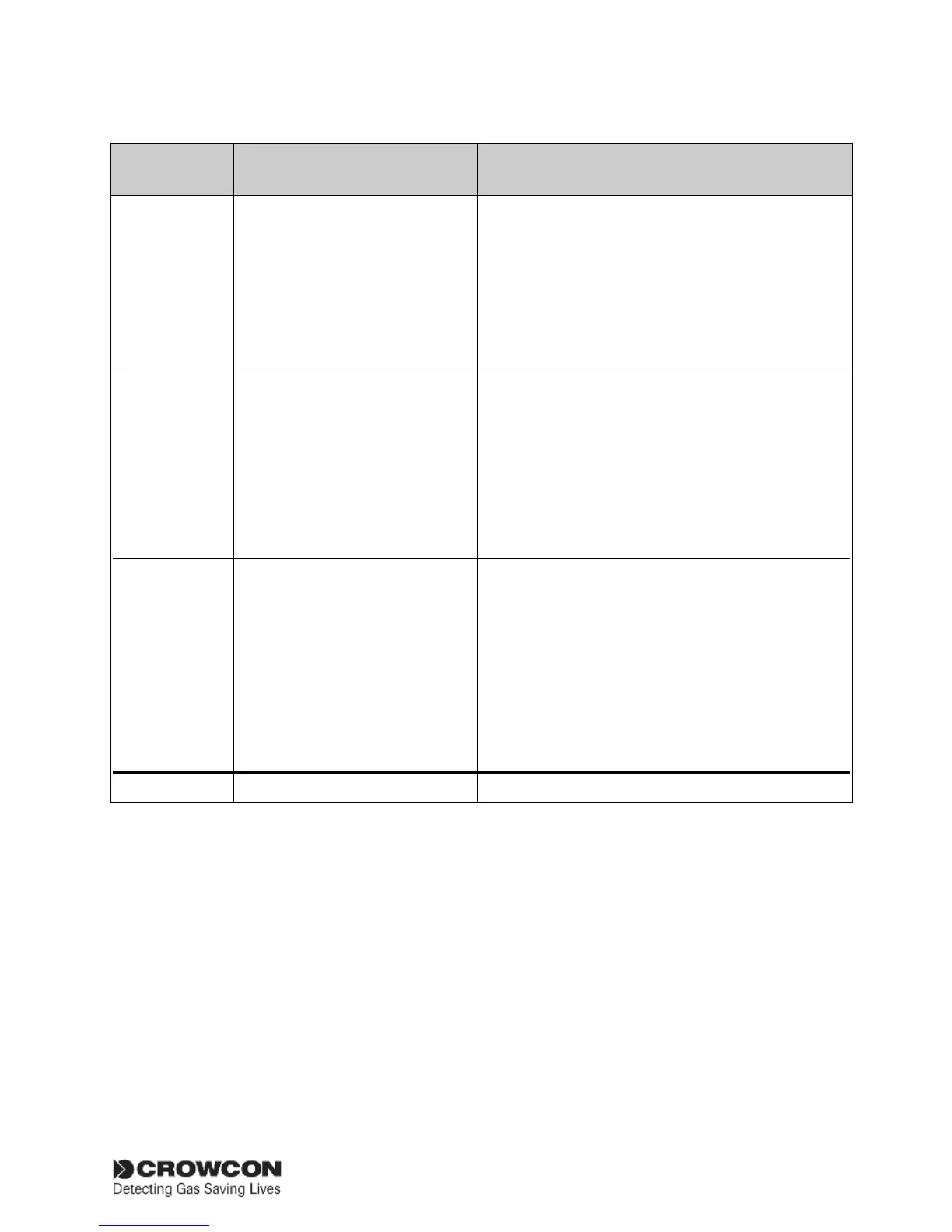
Relay com stat Alarm L1 common
Values = No alarm
In alarm
Alarm L2 common
Values = No alarm
In alarm
Fault common
Values = No alarm
In alarm
Relay chan stat Alarm L1 #1
Values = No alarm
In alarm
Alarm L2 #1
Values = No alarm
In alarm
Output status Output #1
Values = 0.0 to 25.5 mA
Input status Input #1
Values = 0.0 to 66.7 mA,
Supply status Supply
Value = 19.8 to 40 V
Configuration See table Supervisor menu :
* #1 denotes the channel number and therefore may read #2, #3 or #4 on Gasmaster.
Menu Item Values (as shown on display) Description
View menu (shows system status and configuration, but does not allow changes to be made.)
L1 = Level 1.
L2 = Level 2
The 'values' show the current state of each relay
(relays may be normally energised or de-energised
dependant on configuration):
'No alarm' means the relay is in its normal state.
'In alarm' means the relay is in its alarm or fault state.
#1 refers to the input channel, use the Down button
to scroll to channels #2, #3, #4 if appropriate.
L1 = Level 1.
L2 = Level 2 (use the down key to view level 2).
The 'values' show the current state of each relay
(relays may be normally energised or de-energised
dependant on configuration):
'No alarm' means the relay is in its normal state.
'In alarm' means the relay is in its alarm state.
#1 refers to the input channel, use the Down button
to scroll to channels #2, #3, #4 if appropriate.
The 'values' show the current analogue output level
for a channel.
#1 refers to the input channel, use the Down button
to scroll to channels #2, #3, #4 if appropriate.
The 'values' show the current signal input level for
a channel.
Indicates the DC supply level from either the internal
PSU or an external DC supply.