6
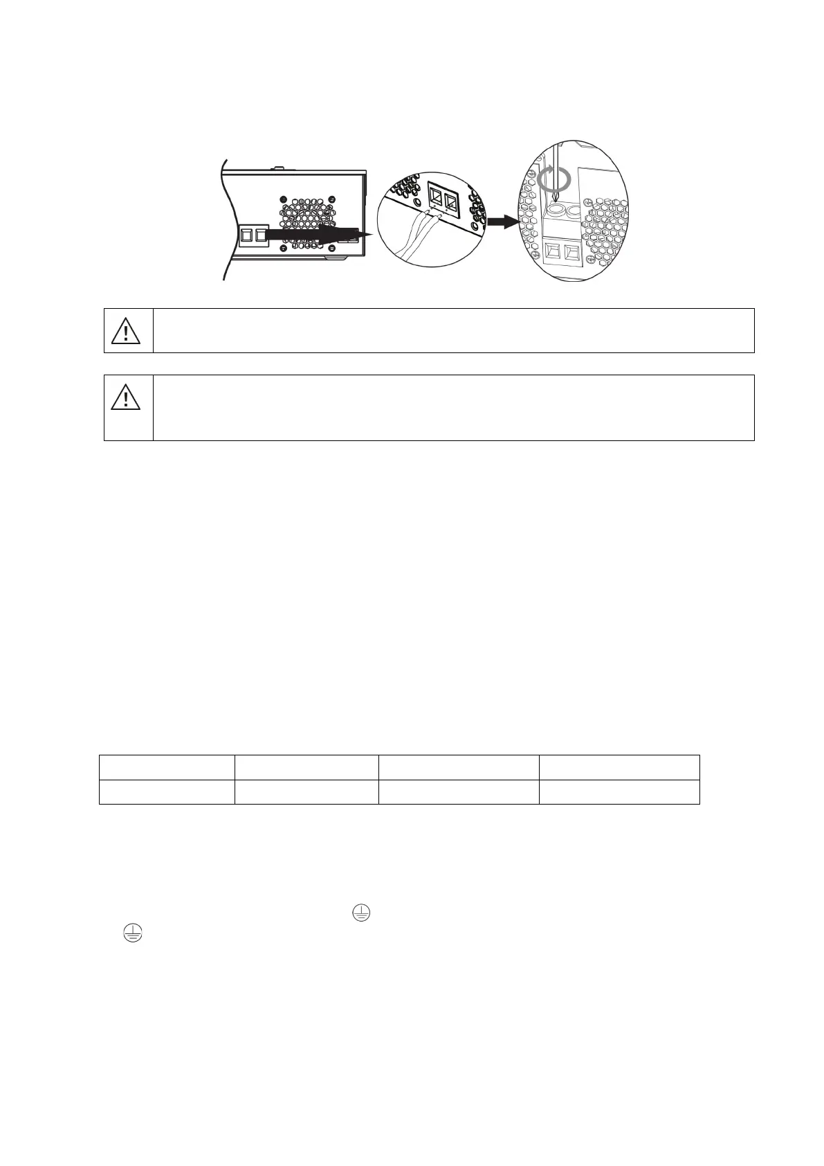
4. Insert the battery wires flatly into battery connectors of inverter and make sure the bolts are tightened with
torque of 2 Nm in clockwise direction. Make sure polarity at both the battery and the inverter/charge is
correctly connected and conductors are tightly screwed into the battery terminals.
Recommended tool: #2 Pozi Screwdriver
WARNING: Shock Hazard
Installation must be performed with care due to high battery voltage in series.
Before making the final DC connection or closing DC breaker/disconnector, be sure
positive (+) must be connected to positive (+) and negative (-) must be connected to negative
(-).
AC Input/Output Connection
CAUTION!! Before connecting to AC input power source, please install a separate AC breaker between
inverter and AC input power source. This will ensure the inverter can be securely disconnected during
maintenance and fully protected from over current of AC input. The recommended spec of AC breaker is 32A
for 3KVA.
CAUTION!! There are two terminal blocks with “IN” and “OUT” markings. Please do NOT mis-connect input
and output connectors.
WARNING! All wiring must be performed by a qualified personnel.
WARNING! It's very important for system safety and efficient operation to use appropriate cable for AC input
connection. To reduce risk of injury, please use the proper recommended cable size as below.
Suggested cable requirement for AC wires
Model Gauge
Cable (mm
2
)
Torque Value
X-3KVA-M 12 AWG
4
0.5 Nm
Please follow below steps to implement AC input/output connection:
1. Before making AC input/output connection, be sure to open DC protector or disconnector first.
2. Remove insulation sleeve 7mm for five conductors.
3. Insert AC input wires according to polarities indicated on terminal block and tighten the terminal screws. Be
sure to connect PE protective conductor (
) first.
→ Ground (yellow-green)
L→ LINE (brown or black)
N→ Neutral (blue)