Page 27Page 26
Reference Manual
Reference Manual
CE 4000 The amp with an Attitude!CE 4000 The amp with an Attitude!
3. If the transformer thermal protection circuit is activated.
4. If amplifier output wires develop a short-circuit.
5. Should the amplifier output stage become non-operational.
The fault status of the amplifier can also be monitored remotely
by attaching a signalling device to the Fault jack located on
the amplifier back-panel. See the Advanced Features and
Options section of this manual for more information on fault
monitoring and suggestions for signalling device circuity.
Some fault conditions may cause the output of the amplifier to
be muted.
Clip Indicator: Two red LEDs (one for each channel) are lo-
cated on the front panel. The Clip indicators turn on when dis-
tortion is audible in the amplifier output.
Signal Indicator: Two green LEDs (one for each channel) are
located on the front panel. Unlike some of our other amplifiers,
the Signal indicators on the CE 4000 amplifier lluminate when
a signal (>–40 dBm) is present at the INPUT
of the amplifier for
that channel. Because these indicators receive the signal be-
fore the level controls, they can be used to troubleshoot wiring
problems within a system. If the Signal indicator for a channel
is not lit, no signal is reaching the amplifier on that channel.
Power Indicator: A green LED is located on the front panel.
The Power indicator lights when your CE 4000 amp has been
turned on and has power.
Level Controls: Two rotary level controls (one for each chan-
nel) are located on the front panel. Use these controls to adjust
each channel’s output. To decrease the level, rotate the control
counter-clockwise (to “
¥
”). To increase the level, rotate it clock-
wise (to “0”).
Input Sensitivity Switch: A three-position Input Sensitivity
switch is located on the back panel near the input connectors.
Your amplifier is shipped from the factory with this switch set to
the 1.4-V position. At this setting , a 1.4-V input signal will drive
the amplifier to full power into an 8-ohm load when the level
controls are turned to maximum. This translates to an amplifier
gain of 33.8 dB or +4 dBu—a level at which most professional
equipment operates.
If required, the Input Sensitivity switch can be moved to the
3.46-volt (26-dB) position, so that the amplifier provides a fixed
voltage gain of 20 (or 26 dB: 1 volt in, 20 volts out). This setting
works best with output levels of +10 dBu (2.5 volts RMS) or
more. Some brands of DJ mixers, in particular, have output
levels in this range.
You can also choose the 0.775-volt setting for a gain of 39.0
dB. This setting operates with a lower-level output and so may
be appropriate for use with consumer-grade CD players and
similar items. Consult the owner’s manual of your input device
for recommended sensitivity settings.
Selecting the correct sensitivity will allow your equipment to
operate at its optimum level and improve the signal-to-noise of
the system.
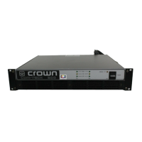
Figure 3.2 Back
Panel Controls

 Loading...