Page 21
Com-Tech Power Amplifiers
Reference Manual
Input and output grounds are sometimes tied together
for testing or metering. This can cause feedback oscil-
lation from load current in the test loop. In some sys-
tems, even the AC power line may provide this feedback
path. To avoid this problem, use proper grounding, iso-
late the inputs and other common AC devices.
Use Good Connectors
1. To prevent possible short circuits, do not
expose the loudspeaker cable connectors.
2. Do not use connectors that might acciden-
tally tie two channels together when making or
breaking connections (for example, a standard
three-wire stereo phone plug).
3. Connectors that can be plugged into AC
power receptacles should never be used.
4. Connectors with low current-carrying ca-
pacity should not be used.
5. Connectors with any tendency to short
should never be used.
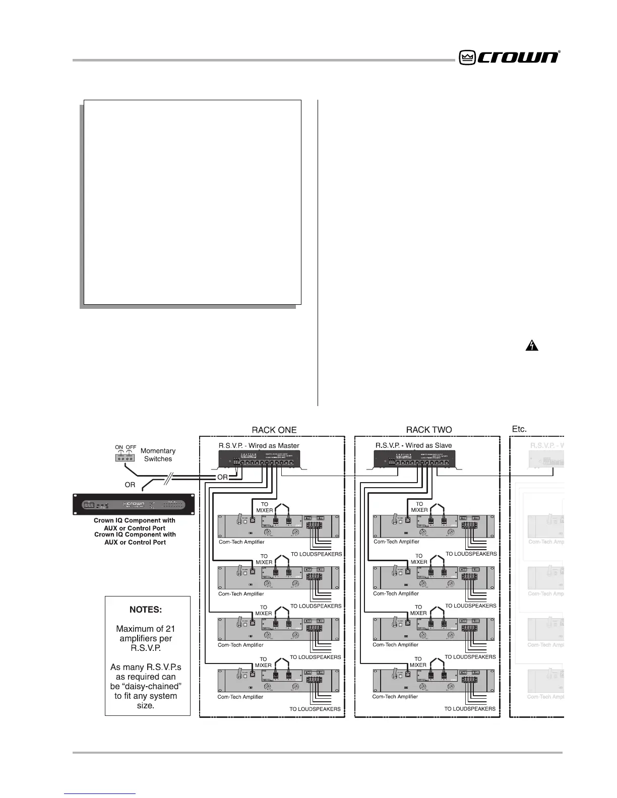
3.3.3 R.S.V.P. Input Connections
The R.S.V.P. accessory module can control racks of am-
plifiers at remote locations, providing a system master
power on/off switching function. A maximum of 21 am-
plifiers can be attached to each R.S.V.P. module; how-
ever, an unlimited number of R.S.V.P. modules can be
slaved together to accommodate any system size.
The power on/off function is controlled from an
IQ-Sys-
tem
®
AUX or Control Port or from a simple remote con-
tact-closure switch. When under IQ System control, all
remote manual-control switches are automatically dis-
abled. This provides priority access to the IQ user and
prevents accidental turnoff. For manual switch configu-
ration, two normally-open momentary switches are re-
quired: one switch provides the signal to turn the unit
on, while the second switch provides the signal to turn
the unit off (see Figure 3.13).
3.3.4 Output Connection
WARNING: Output terminals marked with the sym-
bol are dangerous when live. External wiring connected
to these terminals requires installation by an instructed
person, or should make use of prebuilt wiring and con-
nectors.
Fig. 3.13 Connecting the RSVP Module