Page 17
Com-Tech Power Amplifiers
Reference Manual
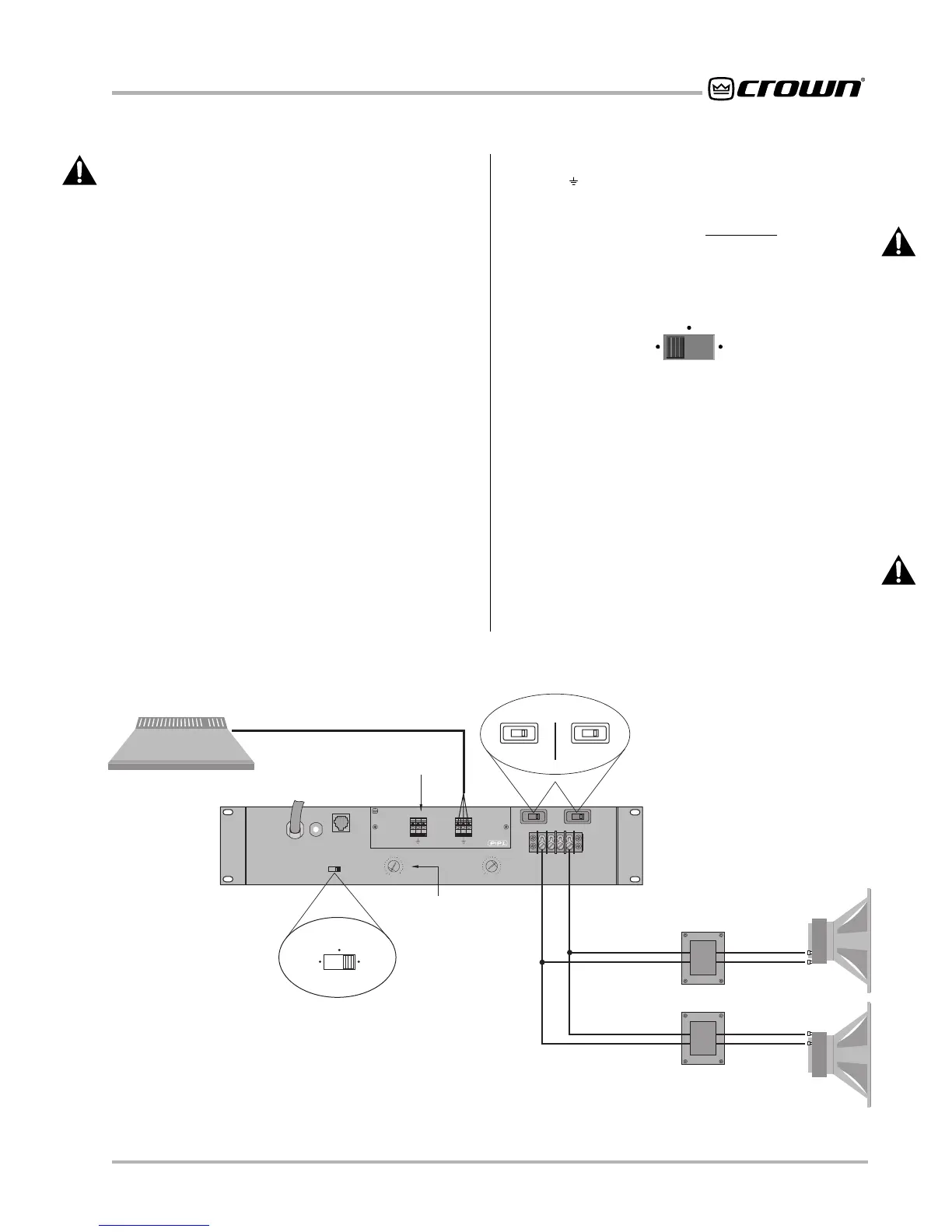
Fig. 3.6 Wiring for Bridge-Mono 70-Volt Mode (140-Volt Output)
COM
+
–
+
140 VOLT STEP-DOWN
TRANSFORMERS
16, 8, OR 4 OHM
16, 8, OR 4 OHM
140 VOLT LINE
MIXER
LOUDSPEAKERS
Com-Tech Amplifier
CHANNEL 1
BRIDGE-MONO
70 VOLT MODE
(140 VOLT OUTPUT)
TURN OFF THE AMPLIFIER
BEFORE CHANGING
THE DUAL/MONO SWITCH.
TURN OFF THE AMPLIFIER
BEFORE CHANGING THE
OUTPUT MODE SWITCHES.
WARNING: BOTH CHAN-
NELS MUST BE SET TO
70 VOLT MODE.
COM
+
–
+
DO NOT
USE
TURN OFF CHANNEL 2 (CCW)
IN BRIDGE-MONO MODE.
DO NOT USE
THE GROUND
TERMINALS
BRIDGE
MONO
DUAL
PARALLEL
MONO
70
VOLT
70
VOLT
8/4
OHM
8/4
OHM
CH1
CH2
CH-2 CH-1
0
dB
.5
1
2
3
4
5
6
7
8
910
11
13
15
17
19
21
25
32
0
dB
.5
1
2
3
4
5
6
7
8
910
11
13
15
17
19
21
25
32
P
R
E
S
S
R
E
S
E
T
PUSH TO RESET
BB
CH2 CH1
+– +–
Programmable
Input Processor (P.I.P.)
REMOTE
WARNING: Both channels must be configured for
the same output mode (8/4-ohm or 70-volt) before
switching to Bridge-Mono mode.
Bridge-Mono wiring is very different from the other
modes and requires special attention. First, turn the
amplifier off. Then select Bridge-Mono mode by sliding
the dual/mono switch to the BRIDGE MONO (right) po-
sition. Both outputs will receive the signal from Channel
1 with the output of Channel 2 inverted so it can be
bridged with the Channel 1 output. DO NOT USE THE
CHANNEL 2 INPUT or the signal level and quality may
be greatly degraded. Also, keep the Channel 2 Input
Attenuation control turned down completely (counter-
clockwise).
Note: The Channel 2 input jack and Input Attenuation
control are not defeated in Bridge-Mono mode. A signal
feeding Channel 2 will work against the Channel 1 sig-
nal, and usually results in distortion and inefficient op-
eration.
Connect the load across the two positive (+) output ter-
minals (see Figure 3.6 and the middle illustration in Fig-
ure 3.7). The positive lead from the load connects to the
positive Channel 1 terminal, and the negative (or
ground) lead from the load connects to the positive
Channel 2 terminal. Do not connect the output
grounds ( ). Also, the load must be balanced (neither
side shorted to ground).
CAUTION: Connect only balanced equipment
(meters, switches, etc.) to the Bridge-Mono output.
Both sides of the line must be isolated from the in-
put grounds or oscillations may occur.
BRIDGE
MONO
DUAL
PARALLEL
MONO
P A R A L L E L - M O N O
Parallel-Mono mode is used to drive loads with a total
impedance of less than 4 ohms when using 8/4-ohm
output mode (see
Bridge-Mono
if the load is greater
than 4 ohms). This mode can also be used to drive a
single high-powered 70-volt constant voltage line.
Parallel-Mono installation is very different from the other
modes and requires special attention.
WARNING: Both channels must be configured for
the same output mode (8/4-ohm or 70-volt) before
switching to Parallel-Mono mode.