Operation Manual
M Series Power Amplifiers
page 8
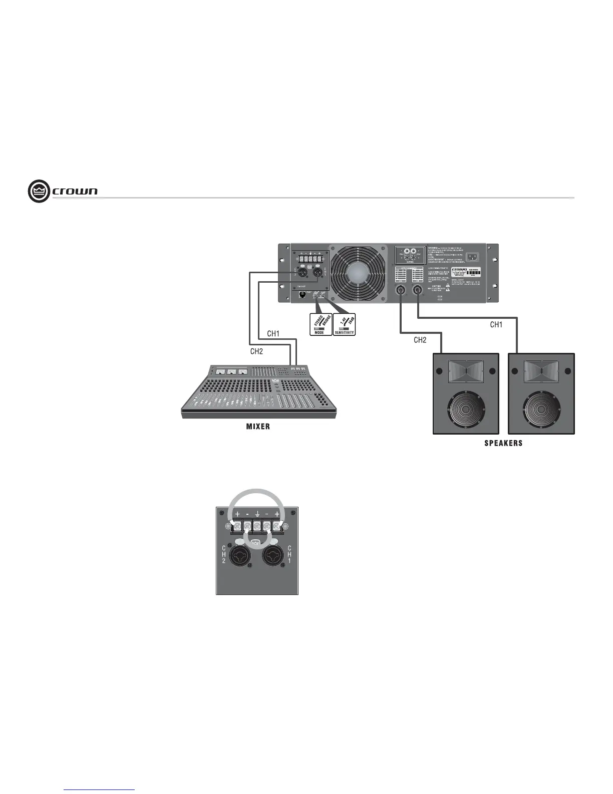
2.6 Wire Your System
2.6.1 Stereo Mode
Typical input and output wiring is shown in
Figure 2.7.
INPUTS: Connect input wiring for both channels.
OUTPUTS: Maintain proper polarity (+/–) on
output connectors.
Connect Channel-1 loudspeaker’s positive (+)
lead to Channel-1 positive (red) terminal of amp;
repeat for negative (–). Repeat Channel 2 wiring
as for Channel 1.
How to Parallel the Inputs in Stereo Mode
There are three ways to feed the same signal to
each amplifier channel:
1. Buy a "Y" cable. Plug the female end into your
signal cable, and plug the split male ends into
both amplifier inputs.
2. Feed your signal to the Channel-1 input
(either barrier-block or Combo). Connect a
jumper wire (Figure 2.8) between the barrier-
block Channel-1 (+) screw terminal and the
Channel-2 (+) screw terminal. Connect another
jumper wire between the Channel-1 (–) screw
terminal and the Channel-2 (–) screw terminal.
3. Feed your signal to the Channel-1 input screw
terminals. Using a mic cable or phone-to-phone
cable, connect Channel-1 Combo jack to Chan-
nel-2 Combo jack.
2 Setup
Figure 2.7
System Wiring, Stereo Mode
Figure 2.8 Jumper Positions to Parallel the Inputs

 Loading...