Commercial Audio Series Mixer-Amplifiers
Operation Manualpage 8
Commercial Audio Series Mixer-Amplifiers
Operation Manual page 9
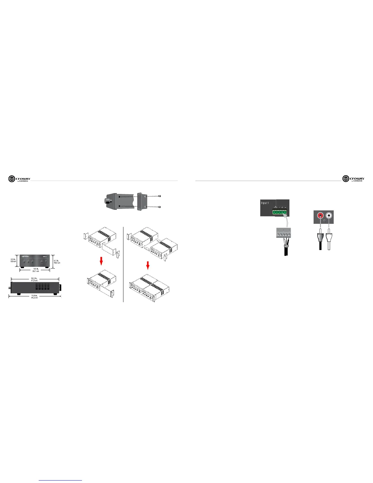
Figure 2.2 How to Connect Rack Ears
(Not to Scale)
2 Setup
2.3 Choose Input Wire and Connectors
Crown recommends using pre-built or professionally wired, balanced
line (two-conductor plus shield), 22-24 gauge cables and connectors.
Unbalanced line may also be used but may result in noise over long
cable runs.
The 135MA and 160MA have two types of input connectors: Phoenix-
type and RCA.
• Mic/Line Connector (CH1): 5-pin Phoenix-type, balanced, pins
3, 4 and 5 (Figure 2.3).
• Dual RCA Input Connector (other channels): For stereo
music signals, unbalanced, summed together, two connectors per
input (Figure 2.4).
Figure 2.3 Mic/Line Connector
Figure 2.1 Dimensions
2.1 Installation
CAUTION: Before you begin, make sure
your mixer-amplifier is disconnected from
the power source, with power switch in the
“off” position and all level controls turned
completely down (counterclockwise).
Use a standard 19-inch (48.3 cm) equipment rack
with an optional rack-mount kit. See Figure 2.1 for
dimensions.
You may also stack mixer-amps without using a
cabinet, or you may place a single mixer-amp on a
surface with 12 inches of air space around the unit
for convection cooling.
NOTE: When transporting in a rack, mixer-amps
should be supported at the front and back.
When using an equipment rack, do not mount units
directly on top of each other. Allow 2 rack units
(3.5 inches) between units for convection cooling.
The side walls of the rack should be a minimum of
two inches (5.1 cm) away from the mixer-ampli-
fier sides, and the back of the rack should be a
minimum of four inches (10.2 cm) from the mixer-
amplifier back panel.
2.2 How to Attach the Unit to a Rack
1. Order the optional Rack-Mount Kit from your
Crown dealer. Part no. RM1 is a “single rack mount
kit” for mounting a single MA unit in a rack. Part
no. RM2 is a “double rack mount kit” for mounting
two MA units side-by-side in a rack.
2. See Figure 2.2. Remove the two screws from
each side of the chassis near the front.
3. Place a rack ear flush with the right front of the
chassis.
4. Insert a screw that you removed into the bottom
hole of the rack ear and chassis. Screw it in.
5. Insert a screw that you removed into the center
hole of the rack ear and chassis. Screw it in.
6. Insert one of the supplied screws into the top
hole of the rack ear and chassis. Screw it in.
7. Repeat steps 3-6 for the left side of the chassis.
Figure 2.4 Dual RCA Input Connectors
To stereo
line-level
source



 To Next Page