Macro-Tech
®
602/1202/2402 Power Amplifiers
Page 20
Reference Manual
4 Operation
4.1 Precautions
Macro-Tech amplifiers are protected from internal and
external faults, but you should still take the follow pre-
cautions for optimum performance and safety:
1. Improper wiring for Stereo, Bridge-Mono and
Parallel-Mono modes can result in serious oper-
ating difficulties. Refer to Section 3.3 for details.
2. WARNING: Do not change the position of the
stereo/mono switch unless the amplifier is first
turned off.
3. CAUTION: In Parallel-Mono mode, a jumper is
used between the red (+) Channel 1 and 2 output
binding posts. Be sure to remove this jumper for
Stereo or Bridge-Mono mode, otherwise high
distortion and excessive heating will definitely
occur. Check the stereo/mono switch on the back
panel for proper position.
4. Turn off the amplifier and unplug it from the AC
mains before removing the PIP module.
5. Use care when making connections, selecting sig-
nal sources and controlling the output level. The
load you save may be your own.
6. Do not short the ground lead of an output cable to
the input signal ground. This may form a ground
loop and cause oscillations.
7. Operate the amplifier from AC mains of not more
than 10% variation above or below the selected line
voltage and only the specified line frequency.
8. Never connect the output to a power supply out-
put, battery or power main. Such connections may
result in electrical shock.
9. Tampering with the circuitry by unqualified person-
nel, or making unauthorized circuit changes invali-
dates the warranty.
Remember: Crown is not liable for damage that results
from overdriving other system components.
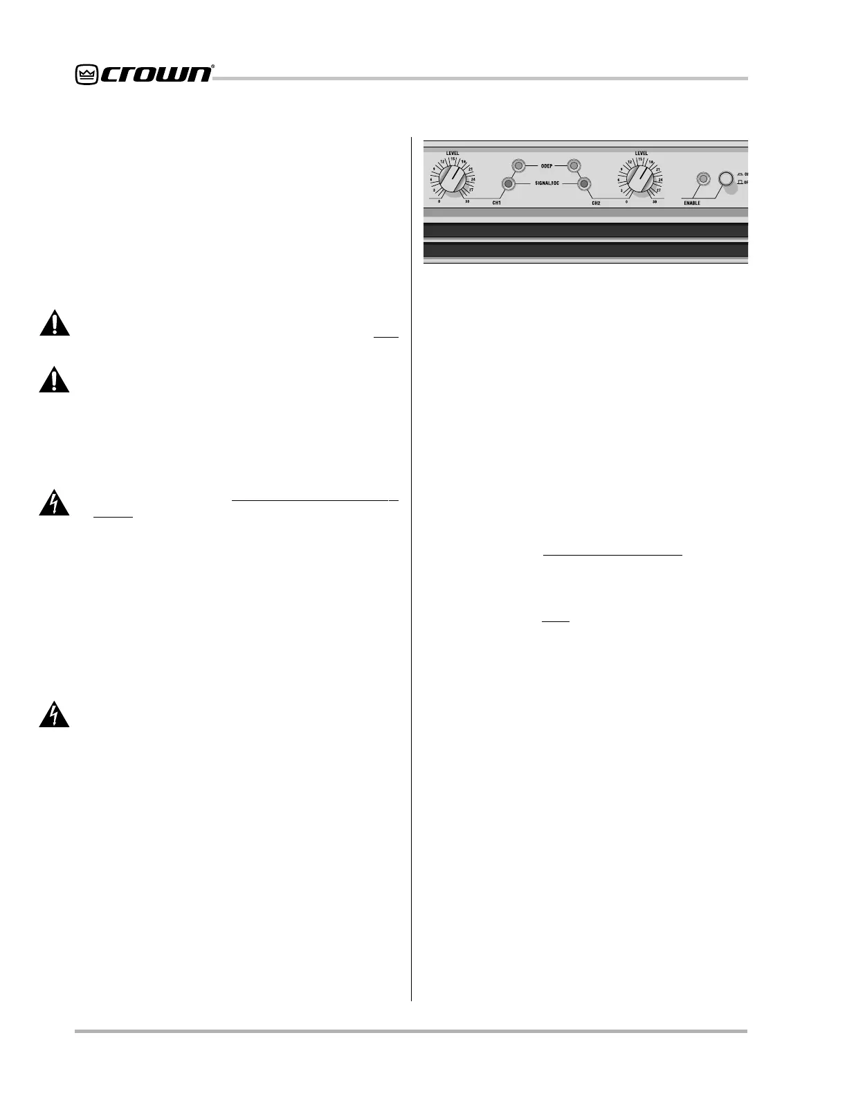
4.2 Indicators
The amber Enable indicator is provided to show that
the amplifier has been turned on (or enabled), and that
its low-voltage power supply and forced-air cooling sys-
tem are working. It does not indicate the status of the
high-voltage power supplies. For example, the Enable
indicator will remain lit during unusual conditions that
would cause the amplifier’s protection systems to put a
Fig. 4.1 Indicators
high-voltage power supply in “standby” mode (see Sec-
tion 4.3.2).
The amber ODEP indicators confirm the normal op-
eration of Crown’s patented Output Device Emulation
Protection circuitry. During normal operation, they glow
brightly to show the presence of reserve thermal-dy-
namic energy. They dim proportionally as the energy
reserve decreases. In the rare event that there is no re-
serve, the indicators turn off and ODEP proportionally
limits the drive level of the output stages so the ampli-
fier can continue safe operation even when conditions
are severe. (For a more detailed description of ODEP,
see Section 4.3.1.)
The ODEP indicator for the affected channel will turn off
if a high-voltage power supply is put in “standby” mode,
a high-voltage power supply fuse (or breaker) blows, or
a transformer activates its thermal protection circuitry
(see Section 4.3.2). Both ODEP indicators turn off if the
amplifier loses AC power, the power switch is turned off
or the low-voltage power supply fuse blows.
The green Signal/IOC indicators show signal presence
and distortion. As signal presence indicators, they flash
with normal intensity in sync with the output audio sig-
nals. As IOC (Input/Output Comparator) indicators, they
flash brightly if there is any difference between the input
and output signal waveforms greater than 0.05%. Be-
cause transient distortion happens quickly, a 0.1 sec-
ond “hold delay” keeps the indicators on long enough
to be easily noticed. The IOC function essentially pro-
vides
proof of distortion-free performance
.
Note: The
Channel 2 IOC indicator will remain lit when running in
Parallel-Mono mode.
Under conditions where one of the amplifier’s high-volt-
age power supplies is temporarily put in standby mode,
the Signal/IOC indicators will stay on with full bright-
ness. They will resume normal operation when the am-
plifier is no longer in standby mode.
Note: See Figure 4.2 for an explanation of the conditions
that may activate standby mode.
 Loading...