6
Installation
-Softener Location / Other Requirements-
• Locate the unit near an unswitched, 120 volt / 60 Hz grounded electrical outlet.
• Check for distance and proper drain installation (e.g. oor drain, washing machine standpipe).
• Determine type and size of piping required for softener connection (e.g. copper, galvanized, PVC plastic).
Note
• If household plumbing is galvanized and you intend to make the installation with copper (or vise versa), obtain
di-electric unions to prevent dissimilar metal corrosion.
• Where the drain line is elevated above the control valve or exceeds 20 feet in length to reach the drain, use 3/4"
I.D. drain line tubing instead of 1/2" I.D. Drain line tubing is not included.
• All plumbing lines not requiring “soft” water should be connected “upstream” of the softener.
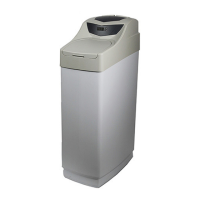
• The cabinet brine tank drain line is gravity ow and must discharge below the overow tting.
• The cabinet brine overow is provided as a back-up in the event the safety oat shut-off should fail, allowing the
brine tank to overll. This drain connection would then carry the excess water to the drain and prevent ooding of
the oor. Therefore, no liability will or can be assumed by the manufacturer of the softener should this occur.
Caution
• If sweat soldering copper pipe (remember to always use lead free solder and ux), cover bypass valve with wet
rags to prevent heat damage to connections and control valve! If using PVC or plastic pipe primers and solvent
cements specically recommended for use with potable water are required.
-Installation Procedure-
- Water Supply Connections and Bypass Valve -
To allow for softener servicing, swimming pool lling or lawn sprinkling, a manual bypass valve has been installed
at the factory. The bypass allows hard water to be manually routed around the softener.
1. Position softener at desired location for installation. (See Installation Diagrams.)
2.Turn OFF main water supply and OPEN nearest faucet to relieve pressure.
3. Cut main line and install appropriate elbows and extensions. Inlet and outlet connections on the control valve are
3/4” FNPT.
Caution: Raised arrows located on the sides of control valve body and bypass valve indicate proper direction of wa
ter ow. Install inlet and outlet piping in direction of arrows. It is recommended that a vacuum breaker be
installed on the inlet plumbing.
4. Rotate bypass valve to the bypass position (position of lever is at right angle to inlet / outlet piping).
5. Turn the main supply line on to restore water service to the home.
6. OPEN nearest faucet to evacuate air and repressurize plumbing lines.
7. Check for leaks!