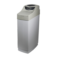
Do you have a question about the CSI Signature Series and is the answer not in the manual?
Guide on how to access the main menu for device settings.
Step-by-step instructions for setting the current time on the control unit.
Procedure to set the AM or PM indicator for the time display.
Instructions for setting hardness in the metered version of the valve.
How to set regeneration frequency for time clock and filter versions.
Method to exit the main menu, including auto-exit conditions.
Describes the normal display alternates between time and water remaining for metered units.
Explains display alternates between time and days until regeneration for time clock units.
Details the battery backup, installation, and features during power failures.
How to initiate a delayed regeneration cycle for metered and time clock versions.
Steps to start an immediate extra regeneration cycle for both versions.
Procedure to quickly advance through regeneration steps using the set/change button.
Shows display for less than 9 minutes remaining in backwash.
Indicates less than 59 minutes remaining in brine/rinse.
Shows display for less than 9 minutes remaining in rapid rinse.
Indicates less than 11 minutes remaining in brine refill.
Shows the unit is in service mode.
Steps to complete the final setup after verifying valve operation.
Lists five error codes and their probable causes and actions.
Instructions to enter the master programming mode by holding buttons.
Configures regeneration type, either timeclock delayed or meter delayed.
Sets days the unit can operate without regeneration in meter mode.
Defines the desired time of day for regeneration cycles to occur.
Programs the duration in minutes for each step of the regeneration cycle.
Configures system capacity in grains for meter delay calculations.
How to exit the master programming mode and return to normal operation.
Diagram illustrating water flow in the service position.
Diagram showing water flow during the backwash cycle.
Illustrates water flow during brine draw and slow rinse.
Diagram depicting water flow during the rapid rinse stage.
Shows water flow during the brine tank refill process.
Guide to replacing key internal components of the valve assembly.
Instructions for removing and installing the valve's powerhead.
Steps for replacing the piston assembly within the control valve.
Continuation of piston assembly replacement steps.
Procedure for replacing internal seals and spacers in the valve.
Instructions for removing and installing the water meter.
How to verify the operation of the drive motor.
Addresses softeners failing to regenerate automatically and causes.
Explains regeneration occurring at the wrong time and its solutions.
Details reasons for loss of water softening capacity and fixes.
Troubleshooting steps for issues related to poor water quality.
Investigates causes for excessive salt consumption by the softener.
Diagnoses and corrects issues causing low water pressure.
Addresses excessive water in brine tank or salty water to service.
Troubleshoots why the softener is failing to use salt correctly.
Solves problems like continuous cycling or flow to the drain.
| Brand | CSI |
|---|---|
| Model | Signature Series |
| Category | Water Dispenser |
| Language | English |