7
-Drain Line Connection-
1. The drain line ow control assembly is pre-assembled for your convenience. Should you choose to hard plumb the
drain line, please remove the barb tting. The ow control housing can be removed by removing the clip and pull
ing straight out on housing.
Note: When re-installing the drain line ow control housing, be sure you hear and feel the O-Ring pop into place
before inserting the clip.
2. Install 1/2” I.D. drain line tubing (not included) from hose barb to an open drain. A 4” gap between end of the drain
line and the open drain is required to prevent waste water backow. Keep the drain line as short as possible. An
overhead drain line can be used if necessary, but should discharge below the control valve. A syphon trap (taped
loop) at the outlet of the drain line is advisable to keep the drain line full and assure correct ow during backwash.
Elbows or other ttings must be kept at a bare minimum.
Note: Where the drain line is elevated above the control valve or exceeds 20 feet in length, 3/4” I.D. drain line tubing
should be used.
-Brine Line and Overow Connection-
1. The brine line tubing is already installed for you.
2. Install 1/2” I.D. drain line tubing (not included) to the overow tting on brine tank located just below the brine
line.
3. Run the opposite end of brine tank drain line to a suitable drain.
Installation
- Electrical Connection and Battery Back Up-
1. Connect one end of power supply into a power cord and the other end into a 115 volt / 60 Hz receptacle.
Note : Do not plug into an outlet controlled by a wall switch or pull chain that could inadvertently be turned off
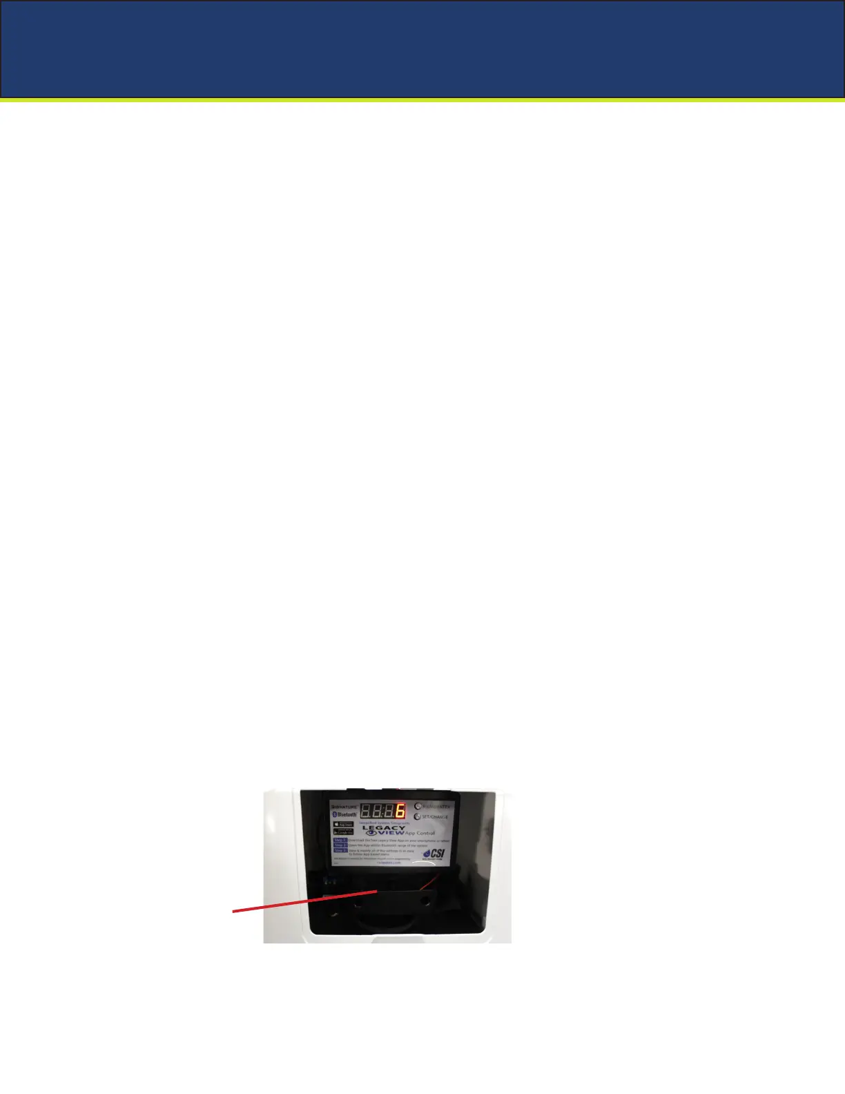
Battery Backup
1. Remove cabinet lid and insert 9 volt battery in valve as shown.
9 Volt Battery