Chapter 2. Installation
20
November 2001
The line fuse is located in an integral-type fuse holder on the
rear panel. Make sure that only fuses of the required rating are
used for replacement. Do not use repaired fuses or short-circuit
the fuse holder. Always disconnect the power cable before
removing or replacing the fuse.
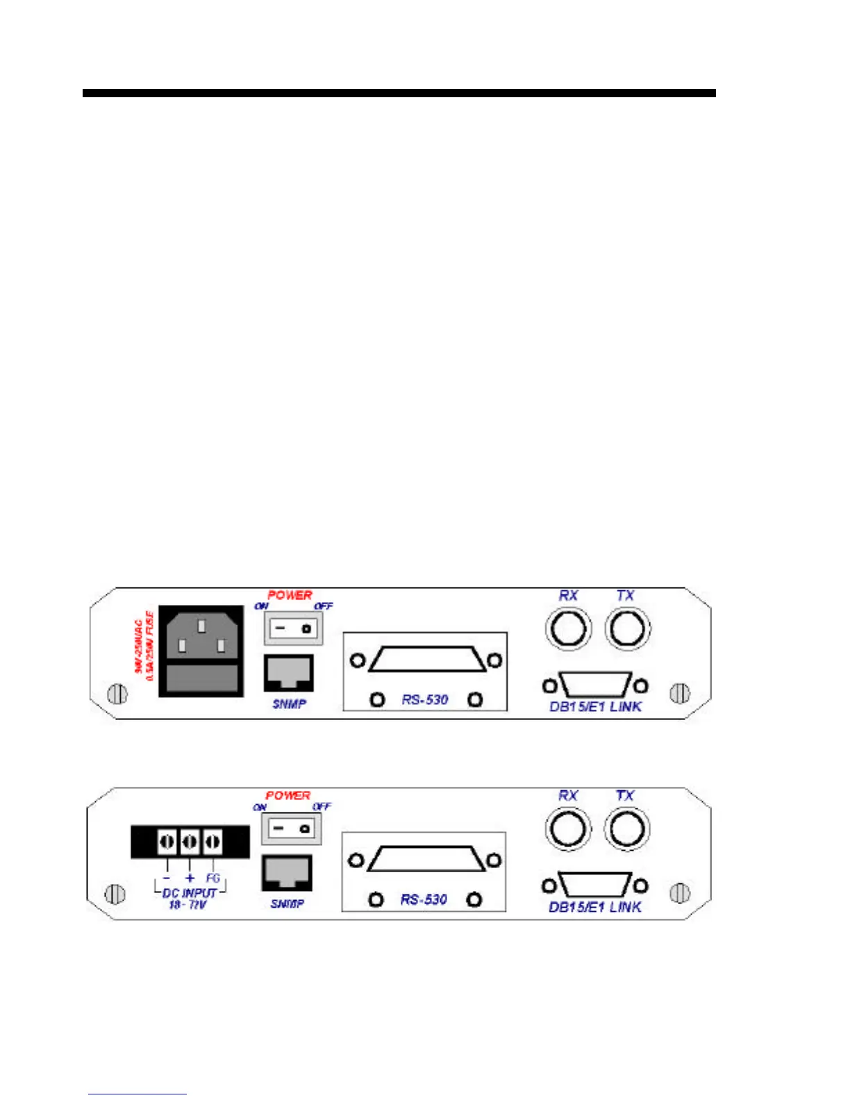
2.4.2 Rear panel connectors
Please refer to the User Data Channels table on page 10 for
a description of the digital interface connectors located on the rear
panel of the ETU-01A (Refer to Figure 2-1). The E1 line
connectors incorporate DB15 pin or two BNC Coax connectors.
(Appendix A provides detailed information on the various interface
modules and connectors).
Figure 2-1 ETU-01A AC rear panel, Option: DCE (RS-530)
Figure 2-2 ETU-01A DC rear panel, Option: DCE (RS-530)
 Loading...