EasyManuals Logo

CTC Union FRM220-CH01 User Manual

CTC Union FRM220-CH01
44 pages
To Next Page IconTo Next Page
To Previous Page IconTo Previous Page
Page #27 background imageLoading...
Page #27 background image
FRM220 Chassis Quick Installation Guide
27
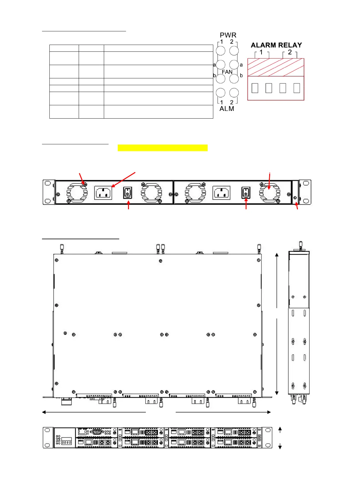
LED Indicators and Alarm Relay
LED
Color
Indication
PWR 1
Green
When On, indicates good power from
module #1
PWR 2
Green
When On, indicates good power from
module #2
FAN a
Green
When On, left fan of power module is OK
FAN b
Green
When On, right fan of power module is OK
ALM 1
Red
When On, NMC has set Alarm 1 ON, relay
1 is closed
ALM 2
Red
When On, NMC has set Alarm 2 ON, relay
2 is closed
Figure. Relays and LEDs
Chassis Rear Description
The rear panel holds the hot-swappable power/fan modules. The pluggable modules do not require
any tools for removal or replacement.
Figure. Chassis Rear View
Chassis Physical Dimensions
Figure. Chassis Dimensions, in millimeters
Cooling Fan (a)
IEC AC Mains Input
Power Module 1
AC Type Shown
Power Module 2
AC Type Shown
Cooling Fan (b)
Protective Earth
(PE) Terminal
482.6mm
44mm
302mm

Table of Contents

Other manuals for CTC Union FRM220-CH01

Questions and Answers:

Question and Answer IconNeed help?

Do you have a question about the CTC Union FRM220-CH01 and is the answer not in the manual?

CTC Union FRM220-CH01 Specifications

General IconGeneral
BrandCTC Union
ModelFRM220-CH01
CategoryChassis
LanguageEnglish

Related product manuals