Link - Multi-color (red/green). Indicates:
a) Status of IP connection
b) Type of transport (EV-DO or 1xRTT)
2.3 Connectors (see Figures 2 and 3 below)
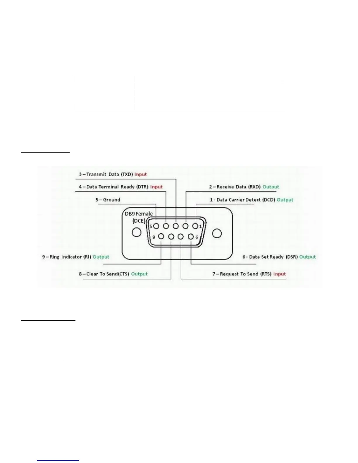
RS232 Connector – This connector is a standard RS232 DCE interface. A straight-through RS232 cable should be used.
The RS232 connector pin out diagram is shown below.
Figure 2 - DB9 Connector
Ethernet Connector
The Ethernet connector on the Z Series is a standard RJ45 connector with auto polarity sensing and can be used with
either a standard Ethernet cable or a reverse (cross over) Ethernet cable.
Terminal Block
Connector J1 supports four separate functions, power, relay contact closure detection, relay driver output, and auxiliary
RS-485 serial port serial data. Contact closure pins 2 and 4 are shared with the auxiliary serial port. To option remove the
circuit board and locate 3-pin headers JP1 & JP2 behind the green connector. Facing the end of the board containing the
green connector JP1 and JP2 should have jumpers center to right to use the discrete I/O (Din, Dout), and JP1 and JP2
should have jumpers center to left to use the auxiliary RS-485 serial port. Auxiliary serial port parameters (baud, parity,
etc.) are set using the RS232/485 configuration screen. From the factory the unit ships with the auxiliary RS-485 serial
port enabled and configured as a master device.