.
The J1 pin out configuration is as follows:
JP1 & JP2 (internal) Center to Right
JP1 & JP2 (internal) Center to Left
Din Src – Discrete Input Source
Din – Discrete Input (See Appendix A)
TR- of RS-485 auxiliary serial port
1
Dout Gnd – Discrete Output Ground
Ground of RS-485 auxiliary serial port
2
TR+ of RS-485 auxiliary serial port
1
Power supply +12VDC (9 – 24VDC)
Power supply +12VDC (9 – 24VDC)
Connect a 120 ohm resistor across pins 2 --> 4 for multi-drop configurations
Available as a third wire ground for use in noisy environments
Discrete output is rated at 200ma @ 24 volts maximum sink current
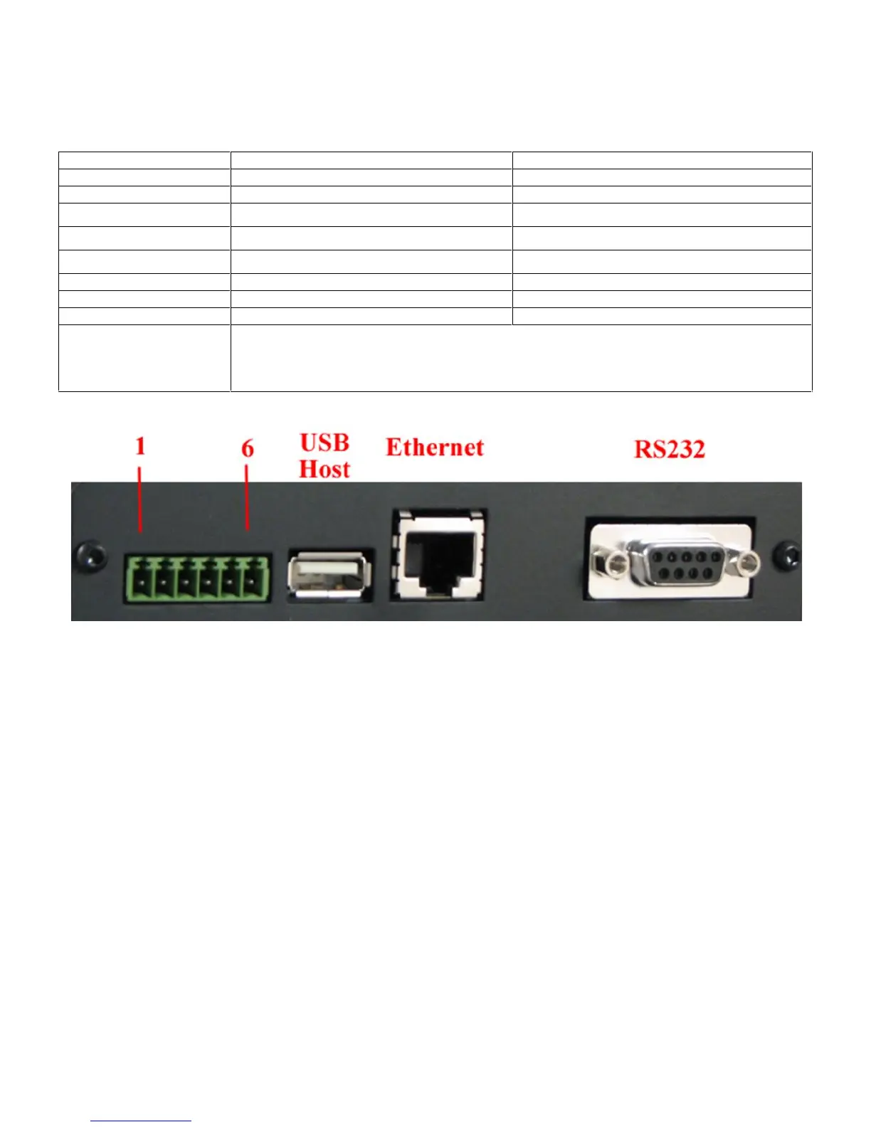
Figure 3 - Z4200U Connectors