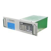
Network Terminal Installation, Operation, and Maintenance Instructions
P/N 8040375G001 3-3
C
HELIX TECHNOLOGY CORPORATION
-
TI CR
Y
OG
E
N
IC
S
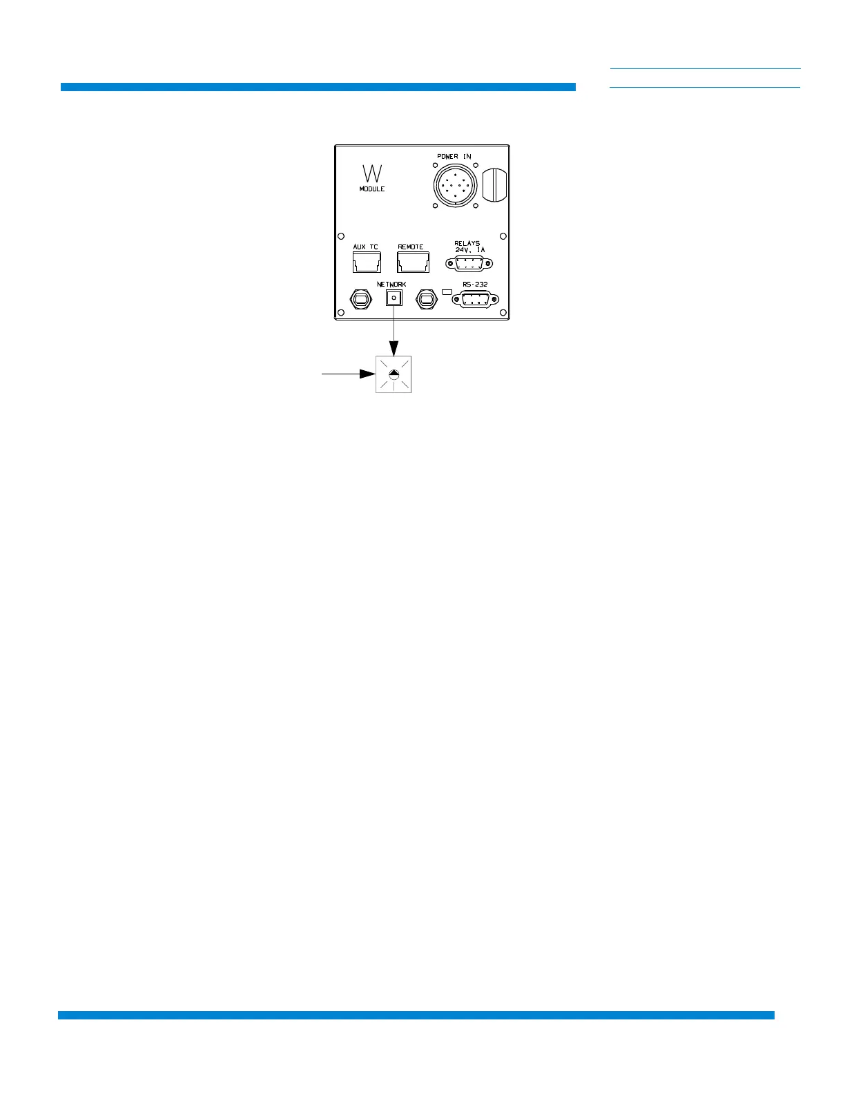
Figure 3-2: Network Selector Switch Location
Power Connections
The Network Terminal is shipped from the factory set to the 110/120 VAC
setting. The input power connector will have to be modified if you plan to
operate the Network Terminal at 220/240 VAC. Follow the appropriate
procedure for your specific operating voltage.
NOTE: The Network Terminal is fused for both 110/120 and 220/240 VAC
operation. Use either size 3AG or 5 x 20mm 0.25 amp fuses when
replacing the fuse.
110/120 VAC
1. Insert the provided power cable plug into the receptacle on the
rear panel of the Network Terminal.
2. Insert the opposite end of the power cable into 110/120 VAC power
receptacle.
NOTE: The bonding stud, as shown in Figure 3-1, is intended for
applications where Electromagnetic Interference (EMI) may be a problem.
It is not to be used as a protective ground. Attach a ground using accepted
EMI grounding practices.
3. If desired, connect an EMI ground conductor to the ground stud.
4. Set the power switch to the ON position.
0
2
4
6
8
Cryopump Network
Selector Switch
 Loading...