Domestic Compact Electrical Systems
86
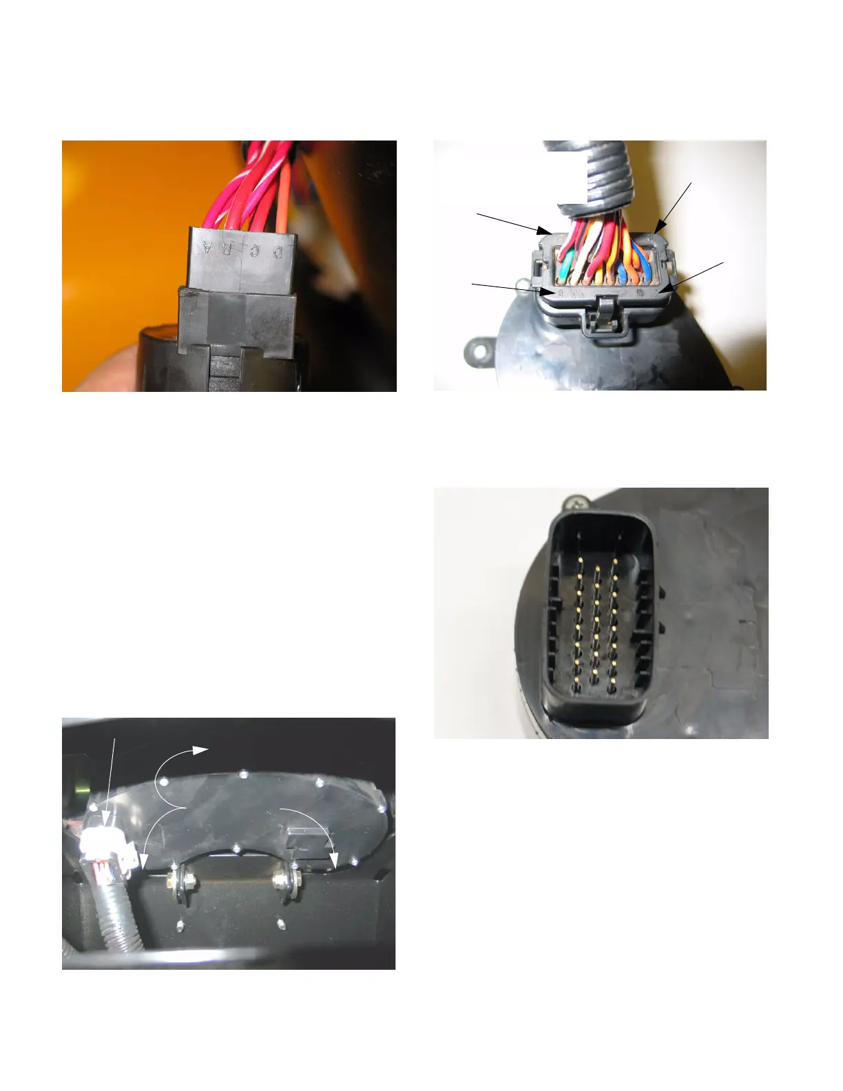
2.11. The key switch has four spade terminals.
See Figure 2.11.
• The red wires with white trace (terminal A & B)
are fused constant hot-leads.
• In the OFF position, no terminals are connected.
• In the RUN position, only terminals B and C are
connected to, sending power through the red
wire with black trace to the lighting and acces-
sory circuits and pin # 18 (run input) on the
instrument panel.
• The START position makes the “RUN” con-
tacts, and A terminal and D terminal are con-
nected to each other, sending power through the
orange wire to pin #16 (start input) on the panel.
2.12. The instrument panel is easily unplugged or
removed with the hood open. See Figure 2.12.
2.13. The pin numbers are indicated on the molded
connector. See Figure 2.13.
2.14. Each number corresponds to a pin position on
the instrument panel. See Figure 2.13.
Figure 2.11
Figure 2.12
Mounting Bolts
Molded connector
Figure 2.13
“8”
“1”
back row: # 16 -> # 23
center row: # 9 -> # 15
near row: # 1 -> # 8
“16”
“23”
Figure 2.14
Pins on instrument
panel connection
www.mymowerparts.com
K&T Saw Shop 606-678-9623 or 606-561-4983

 Loading...