Domestic Compact Electrical Systems
87
2.15. The pin identities are as follows:
See Figure 2.15.
2.16. The reverse over-ride switch is located on the
rear fender. On all Series 5000, 6000 and
domestic 7000 tractors, the fenders must be
removed to reach the switch. See Figure 2.16.
Pin-out chart
Pin Signal
1 Cruise Control Input
2 Oil pressure
3 Headlights
4 Reverse over-ride
5PTO ON
6PTO relay
7 Fuel Gauge unit
8 Ground, -
9 Reverse
10 Left arrow
11 Glow plugs
12 Tachometer sending unit
13 Magneto
14 Cruise control magnet
15 12 volts, +
16 Start input
17 Temp sender unit
18 Run input
19 Open
20 Brake on
21 Right arrow
22 Open
23 Open
Figure 2.15
Figure 2.16
Reverse
over-ride
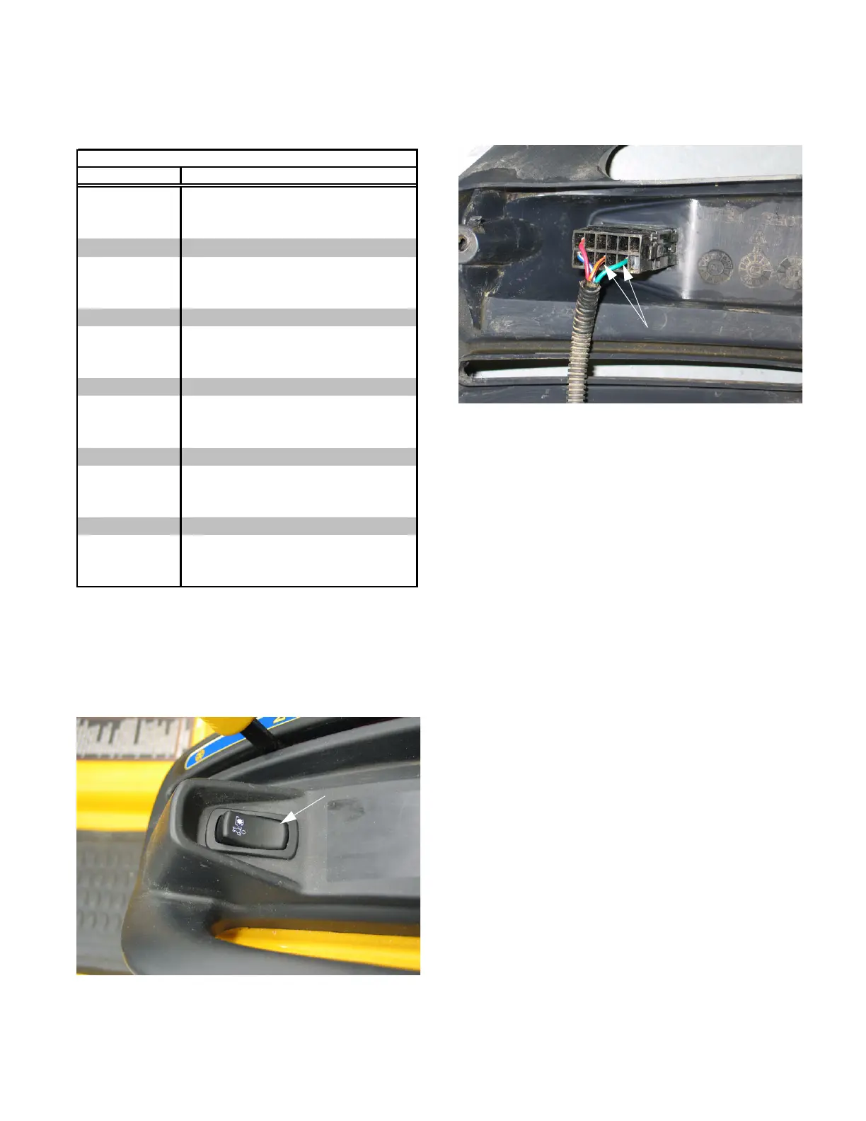
2.17. On Series 6000 and domestic Series 7000, there
are four wires to the switch. See Figure 2.17.
• There are two sets of contacts in the reverse
over-ride switch on the series 7000 tractor: one
set normally open, and one set normally closed
• Engaging the reverse over-ride sends a ground-
signal to the instrument panel through the
orange and black wire by closing contacts that
connect it to the green ground wire.
• Engaging the reverse over-ride breaks the sec-
ond set of contacts, between red wire with black
trace (auxiliary power) the blue wire with white
trace (pin #1 on instrument panel). This shuts-
off power to a cruise control feature that was
facilitated in the wiring harness but did not go
into production.
2.18. On series 5000 tractors, only the orange wire
with black trace and the green wire are present.
Engaging the reverse over-ride sends a ground-
signal to the instrument panel through the
orange and black wire by closing contacts that
connect it to the green ground wire.
Figure 2.17
Four-wire reverse
over-ride:Series
6000 and 7000
Two-wire reverse
over-ride: series 5000
www.mymowerparts.com
K&T Saw Shop 606-678-9623 or 606-561-4983
 Loading...