EasyManua.ls Logo

Cub Cadet Domestic Series 7000 User Manual

Cub Cadet Domestic Series 7000
88 pages
To Next Page IconTo Next Page
Page #1 background imageLoading...
Page #1 background image
Service Manual
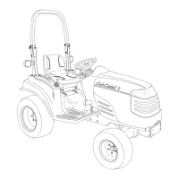
Domestic Series 7000 Compact Tractor
MTD Products Inc. - Product Training and Education Department
FORM NUMBER - 769-01634
12/2004
NOTE: These materials are prepared for use by trained technicians who are experienced in the service and repair of equipment of the
kind described in this publication, and are not intended for use by untrained or inexperienced individuals. Such individuals should seek
the assistance of an authorized service technician or dealer. Read, understand, and follow all directions when working on this equip-
ment. This includes the contents of the Operators Manual, which came with your equipment. No liability can be accepted for any inac-
curacies or omission in this publication, although every care has been take to make it as complete and accurate as possible. The right
is reserved to make changes at any time to this document without prior notice and without incurring an obligation to make such
changes to previously published documents. All information contained in this publication is based on product information available at
the time of publication. Photographs and illustrations used in this publication are for reference use only and may not depict actual
model and component parts.
Question and Answer IconNeed help?

Do you have a question about the Cub Cadet Domestic Series 7000 and is the answer not in the manual?

Cub Cadet Domestic Series 7000 Specifications

General IconGeneral
BrandCub Cadet
ModelDomestic Series 7000
CategoryTractor
LanguageEnglish

Summary

STANDARD HYDRAULIC SYSTEMS ON THE DOMESTIC SERIES 7000: ORIENTATION

1.1. The transmission housing acts as a reservoir

Transmission housing serves as reservoir for hydraulic systems like hydrostatic drive, steering, and lift.

1.4. The hydrostatic drive is a Sauer model BDU15.

Identifies the hydrostatic drive as a Sauer model BDU15 with an integrated charge pump.

1.5. The steering and lift cylinder are powered by

Explains that steering and lift cylinders are powered by a Sauer-Danfoss auxiliary pump.

HYDROSTATIC DRIVE: BASIC OPERATION

2.4. The lower part of the pump contains a fixed

Describes the fixed displacement axial piston hydraulic motor in the hydrostatic drive.

2.5. The hydro. control arm (scissors bracket) moves

Explains how the control arm moves the swash plate to control pump output direction.

2.8. The charge pump maintains a supply of pressur-

Describes the charge pump's role in supplying pressurized fluid for lubrication and feeding.

2.9. The charge check valves direct the flow of pressur-

Explains how charge check valves direct flow to pump pistons and reverse flow direction.

EXTERNAL CHECKS

3.2. If the transmission creeps, or the tractor fails

Advises checking neutral control and linkages if transmission creeps or speed is low.

3.4. If the tractor fails to achieve normal ground

Guides checking for brake drag if ground speed is poor and pump noise is unusual.

FLOW AND PRESSURE TESTS: HYDROSTATIC DRIVE

5.2. Clean the area surrounding the set screw

Instructs on cleaning and removing the set screw to access the hydrostat test port.

5.3. Connect a gauge that is capable of reading

Details connecting a pressure gauge to the test port using appropriate fittings.

5.4. The charge pump should generate between 70

Specifies the expected pressure range for the charge pump at a given RPM.

5.5. As the RPM is increased to the governed top

Advises observing pressure changes with increased RPM and troubleshooting if pressure drops.

AUXILIARY PUMPS

6.1. The standard auxiliary pump provides pressure

Details the function of the standard auxiliary pump for steering and lift.

6.5. As with the hydrostatic drive, confirm that the

Lists preliminary checks for auxiliary pump drive, supply, and fluid condition.

STEERING PUMP AND CYLINDER

7.1. Two steering units have been used in domestic

Identifies the two types of steering units used: Sauer/Danfoss and Ross.

7.2. Identification: The Sauer OSPM 63 PB unit

Explains how to visually distinguish between Sauer and Ross steering units by their body shape.

7.5. The following set of symptoms, causes, and

Introduces a guide for diagnosing steering issues by symptoms, causes, and solutions.

HYDRAULIC LIFT CYLINDER AND CONTROL VALVE

8.1. If the hydraulic lift cylinder does not work

Advises visual inspection of the lift cylinder, linkage, and feedback rod for issues.

8.2. If the lift cylinder is operable, run it through

Lists normal operating characteristics of the lift cylinder, including feedback rod function.

TANDEM PUMP

LOADER VALVE

10.5. With the test kit installed as shown, pushing the

Details testing the loader valve by pushing it to the detent and observing flow/pressure.

Domestic Series 7000 MFD

1. TO IDENTIFY THEM MFD:

Provides methods to identify the Cub Cadet-built MFD versus the outsourced MFD.

Domestic Compact Electrical Systems

1. SIMILARITIES AND DIFFERENCES BETWEEN SYSTEMS:

Compares electrical systems across Series 5000, 6000, and 7000 tractors.

COMPONENTS

1.13. Charging system diagnosis: Flywheel charging

Guides diagnosing flywheel charging systems using specific tools.

Domestic Compact Dash and Steering Pump

1. DASH PANEL REMOVAL

Details the procedure for removing the dash panel.

STEERING SHAFT AND PUMP: SAUER

STEERING SHAFT AND PUMP: ROSS

Domestic Series 7000 Damped Driveshaft

2. DRIVESHAFT REMOVAL

Provides step-by-step instructions for removing the driveshaft.
Related product manuals