Domestic Compact Electrical Systems
73
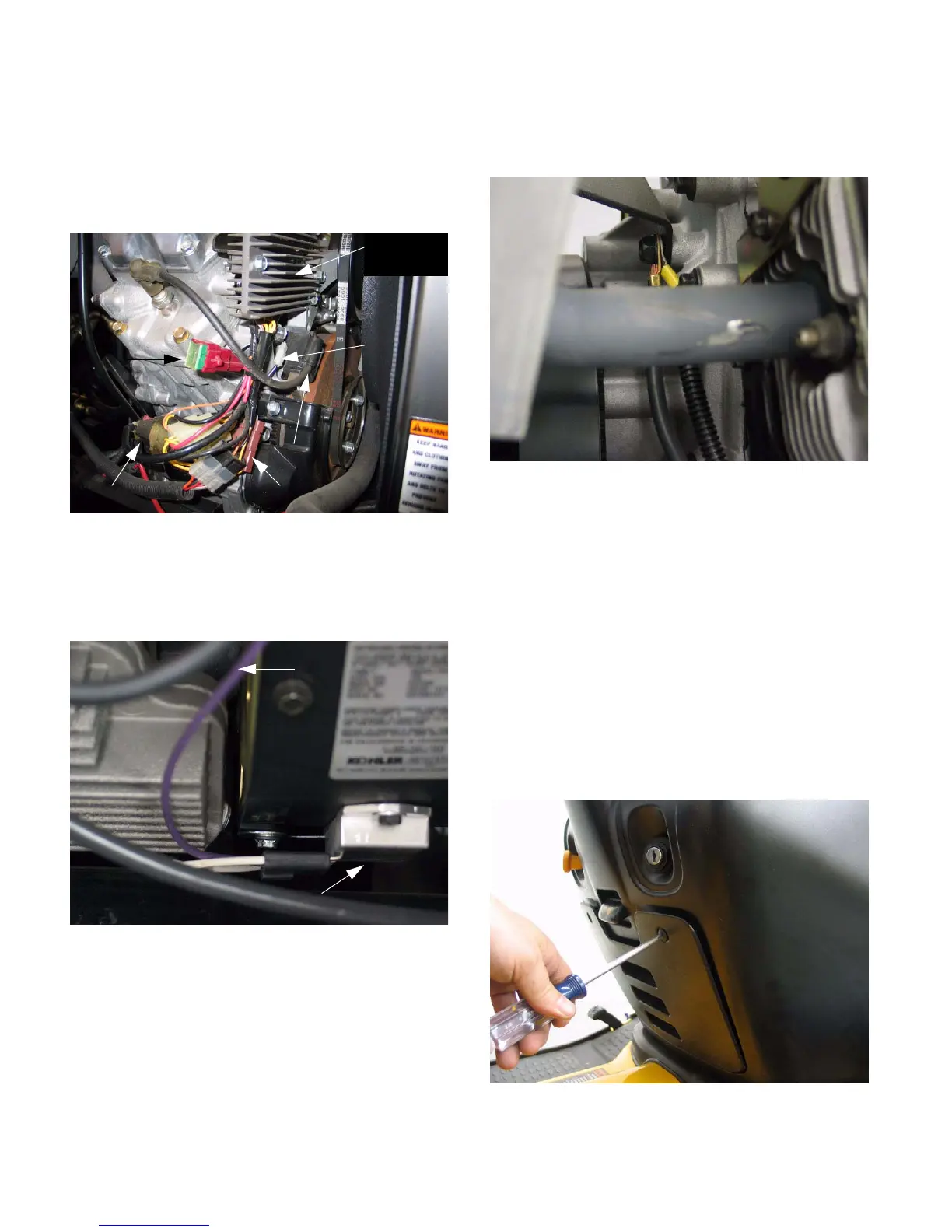
1.11. The gasoline engines use flywheel mounted
rotors and engine mounted stators to generate
A.C. current. The current is processed through
regulator-rectifier modules before being passed
to the main harness of the tractor.
See Figure 1.11.
1.12. Systems vary slightly between engine manufac-
turers, but principles of operation are compara-
ble. See Figure 1.12.
1.13. Charging system diagnosis: Flywheel charging
systems can be diagnosed using the Briggs &
Stratton shunt (B & S part # 19468) or inductive
ammeter and DVOM. Charging systems on the
diesel engines are similar enough to automotive
designs that an automotive type AVR tester (eg.
Snap-On MT3750) can be a feasible alternative
1.14. As with all electrical systems, do not neglect the
basics: clean connections and good ground
paths. See Figure 1.14.
2. COMPONENTS
2.1. The heart of the electrical system is in the dash
panel. It is some components are accessible
from beneath the hood, others may be reached
by removing the access panel. See Figure 2.1.
Figure 1.11
Kawasaki starter
Regulator
/ rectifier
Charging
circuit fusible
link (40A)
Mag.ground
(kill) wire
Connector(raw alternator power)
Magneto
Figure 1.12
Regulator / rectifier (Kohler engine)
Raw Alternator
out-put
Figure 1.14
Figure 2.1

 Loading...