Domestic Compact Dash and Steering Pump
67
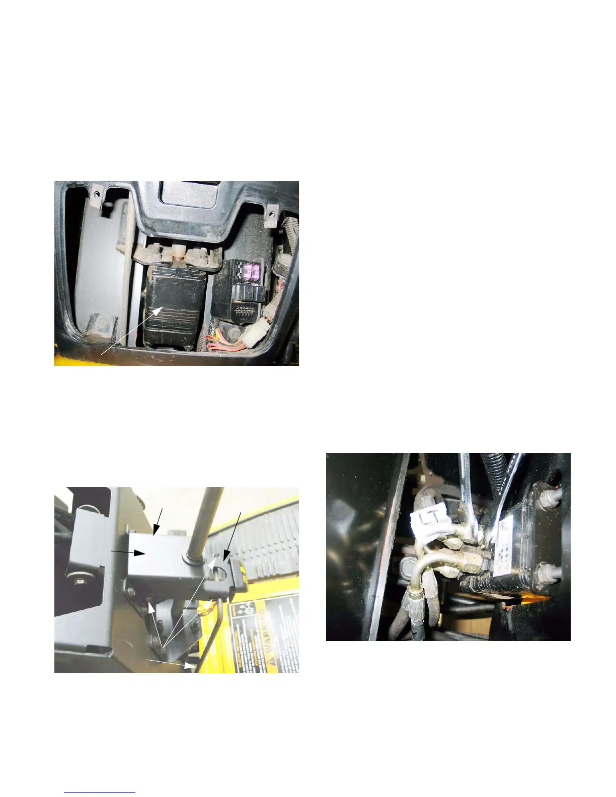
4. STEERING SHAFT AND PUMP: ROSS
4.1. Series 7000 tractors built during and after the
2004 model year, and all 5000 series tractors
are equipped with a Ross steering pump. The
body of the Ross pump is square in cross sec-
tion. Flare fittings that connect to the hydraulic
lines are located on the bottom end of the pump.
See Figure 4.1.
4.2. To access the steering shaft and pump, remove
the dash panel as described in the dash panel
removal section.
4.3. Remove the hairpin clips that secure the parking
brake rod to the brake lever bracket.
See Figure 4.3.
Figure 4.1
Sauer pump: square body
Figure 4.3
Hairpin clips
Parking brake rod
Brake lever
bracket
Clevis pin
Steering
column
bracket
4.4. Remove the hairpin clip and clevis pin that
secure the brake lever bracket to the steering
column bracket. The steering shaft passes
through the brake lever bracket.
4.5. Remove the four bolts that hold the steering col-
umn bracket to the pedestal using a 3/8” wrench.
4.6. Clean the area surrounding the steering pump
hydraulic connections and mark the hydraulic
lines connected to the steering pump to ease
installation: See Figure 4.6.
• The hose at the top left side of the steering
pump (“RT” port) goes to the base end of the
steering cylinder.
• The hose at the top right side of the steering
pump (“LT” port) goes to the shaft end of the
steering cylinder.
• The hose beneath the “RT” port of the steering
pump (“IN” port) goes to the top fitting on the
hydraulic pump.
• The hose beneath the “LT” port of the steering
pump (“OUT” port) goes to the forward-facing
elbow on the return manifold.
• The hose beneath all of the others (“AUX” port)
goes to the bottom port on the hydraulic control
valve.
• An 11/16” wrench will fit the fittings and the
adaptors.
NOTE: There is a port diagram on the steering
pump.
Figure 4.6
VIEW: Front side
of Sauer pump,
accessible behind
dash panel

 Loading...