Domestic Series 7000 Hydraulics
24
10. LOADER VALVE
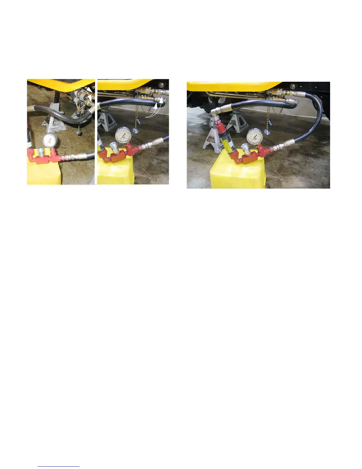
10.1. the simplest way to check pressure to the
attachment is by connecting the test kit to the
Quick Disconnect ports. See Figure 10.1.
• Connecting to the outboard pair of hydraulic
tubes will give a reading when the loader valve
lever is moved forward or back.
• Connecting to the inboard pair of hydraulic tubes
will give a reading when the loader valve lever is
moved from side to side.
• Connect to the inboard set of tubes, or the out-
board set of tubes. Do not connect to the top set
or the bottom set.
• One female quick disconnect and one male
quick disconnect will be required on the test kit.
10.2. If the performance problem is isolated to one
dimension of movement, connect first to the set
of tubes that is associtated with that dimension.
10.3. After the test kit is connected, confirm that no
unsafe conditions will result from starting the
engine or operating the hydraulic system.
10.4. Open the flow valve on the test kit completely,
then start the engine, and set the throttle to
maintain 3,000 RPM.
10.5. With the test kit installed as shown, pushing the
loader valve forward to the detent will generate a
reading on the flow meter of about 6.6 GPM (25
L/m) when the test kit flow valve is open. Pres-
sure will be zero. See Figure 10.5.
NOTE: Pushing the loader valve lever all the
way forward, past the detent, will put the valve
into “float” mode. This is reflected by a flow
meter reading that falls to zero, and a pressure
gauge reading falls to zero.
NOTE: Pushing the loader valve lever forward,
but not all the way to the detent will produce
readings with less flow, but increased pressure.
10.6. Reducing throttle to the 1,200-1,500 RPM range,
observe the flow while pushing the loader valve
lever forward to the detent. The flow should be
around 4 GPM (15 L/m).
Figure 10.1
Connected to
inboard couplers
Connected to
outboard couplers
Figure 10.5

 Loading...