Domestic Series 7000 Hydraulics
25
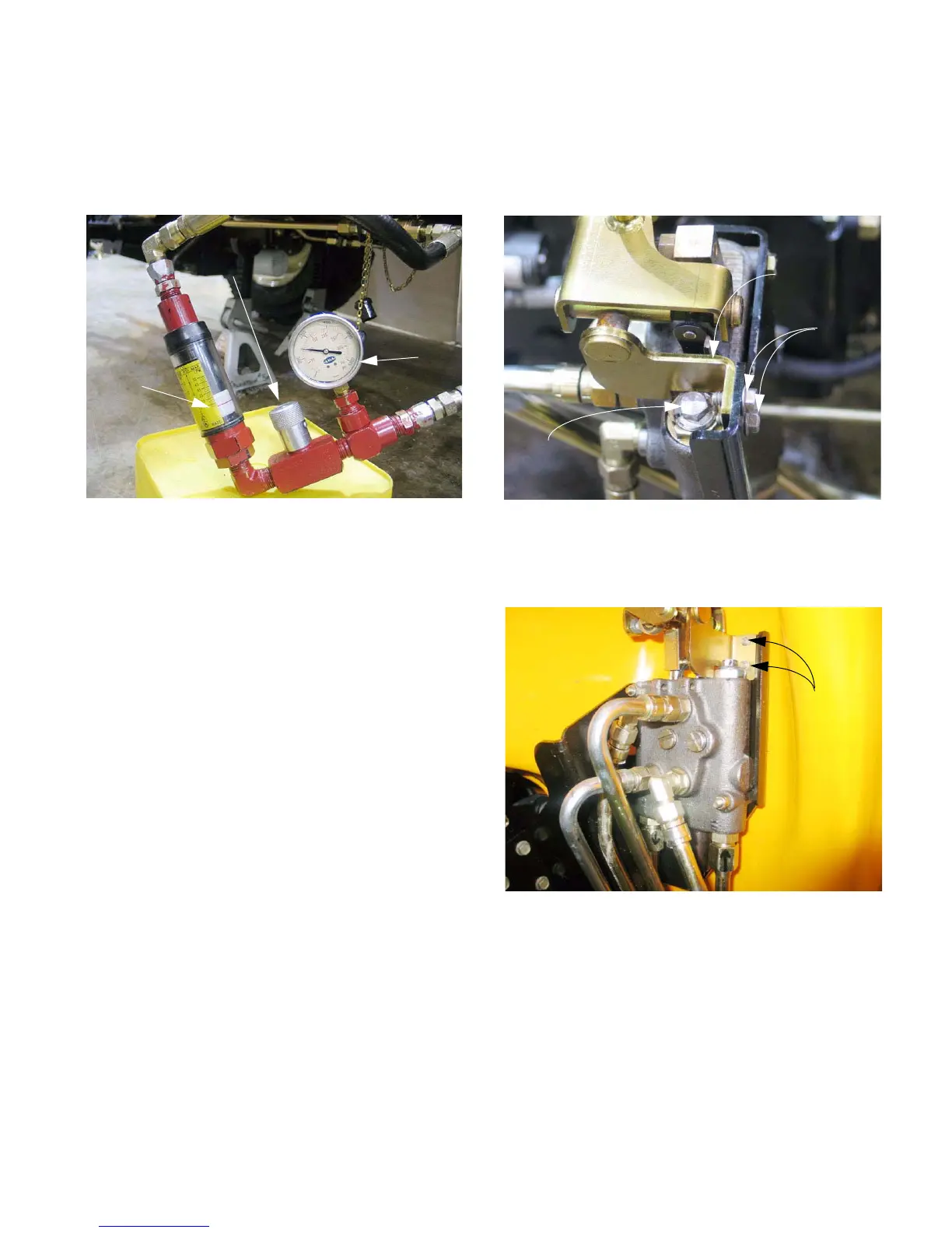
10.7. While holding the loader valve lever forward,
close the flow valve on the test kit. Because
there is a pressure relief feature in the loader
valve, the pressure should rise to 1,500 PSI (103
Bars) and hold steady. See Figure 10.7.
NOTE: Because of the relief feature built into the
loader valve, as pressure aproaches the relief
point of 1,500 PSI (103 Bars) more fluid will be
diverted to the return manifold. As more fluid is
diverted, the flow meter will show progressively
lesser readings. If the flow valve on the test kit
is closed completely, flow will stop completely.
CAUTION: If pressure rises substantially above
1,500 PSI (103 Bars) discontinue the test imme-
diately. Correct the pressure relief issue before
continuing.
10.8. If the pressure varies slightly in either direction,
the relief valve can be adjusted. It is located on
the top, outboard corner of the loader valve.
10.9. In order to adjust the relief valve, it is necessary
to remove the fenders. The fender removal pro-
cess is described in detail in the 2003 Cub Cadet
Technical Handbook, page 6-21 through page 6-
26.
Figure 10.7
Flow meter
at zero
Pressure
gauge at
1,500 PSI
(103 Bars)
Flow valve
closed
10.10.It is necessary to unbolt the pivot bracket
assembly from the loader valve in order to get a
wrench on the relief valve adjustment screw.
The pivot bracket can be unbolted using a 3/8”
wrench. See Figure 10.10.
10.11. The pivot bracket bolts are inaccessible without
removing the fender. See Figure 10.11.
10.12.Once access is gained to the adjustment screw,
index the screw, jam nut, and housing using a
marker.
Figure 10.10
Releif valve
adjustment
screw
Pivot bracket
Pivot bracket
bolts
Figure 10.11
Pivot
bracket
bolts

 Loading...