Domestic Compact Electrical Systems
80
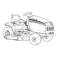
2.22. The reverse switch on the series 6000 and 7000
tractors operates in the same manner to control
the PTO clutch. See Figure 2.22.
• The reverse switch on Series 6000 and Series
7000 domestic compact tractors is located on
the right side frame channel, just ahead of the
pedal linkage.
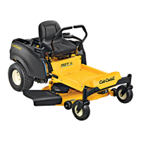
• The second set of contacts in the switch is nor-
mally open.
• When the plunger is depressed (in reverse), the
contacts close, enabling power to pass form the
red wire with black trace (power) to the white
wire that feeds power to the back-up lights.
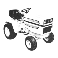
2.23. The brake switch for the Series 5000 compact
tractor is located on the left hand side frame
channel, just in front of the pedal linkage, with
the plunger vertical (up). See Figure 2.23.
Figure 2.22
Reverse switch:
Series 6000 and 7000
Figure 2.23
Brake switch:
Series 5000
2.24. The brake switch on the Series 5000 tractor con-
tains three sets of contacts. See Figure 2.24.
• All three sets are normally open: when the brake
is not applied, the plunger is up, and none of the
circuits connected to the switch have continuity
through the switch.
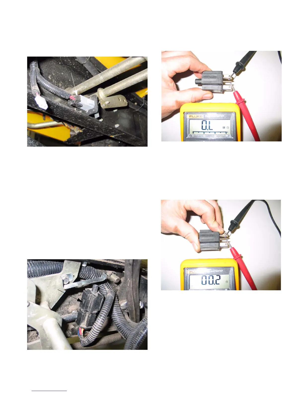
2.25. Depressing the plunger (brake applied) closes
all three sets of contacts. See Figure 2.25.
• With the plunger depressed, each pair of spade
terminals that are adjacent to one another (flat
side to flat side) will have continuity.
Figure 2.24
Plunger up:
Open Line
Figure 2.25
Plunger down:
contacts closed

 Loading...