Domestic Compact Electrical Systems
79
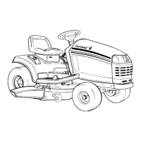
2.19. The fuel tank sender unit also lives under the
fender, on the left hand side. It is basically a
potentiometer actuated by a float. It creates
more or less resistance between the white wire
leading to pin #7 on the instrument panel and a
ground circuit. See Figure 2.19.
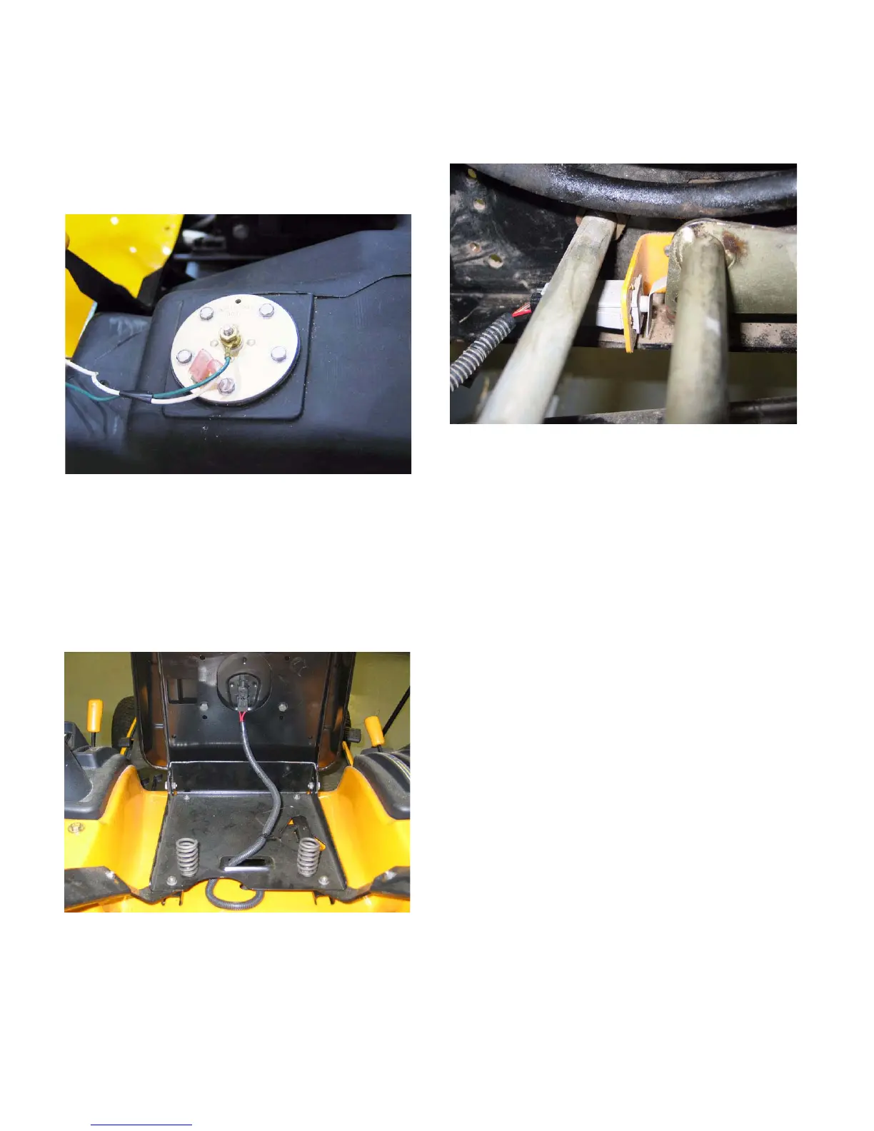
2.20. The seat switch contains a set of normally open
contacts. When the seat is occupied, power is
sent to the PTO relay windings. When the seat
is empty, the PTO relay is de-energized, braking
the contact that provides power to the PTO. We
never want the PTO running with the seat
empty. See Figure 2.20.
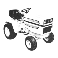
2.21. The reverse switches differ between the Series
5000 tractor and the other domestic compact
tractors. See Figure 2.21.
• The series 5000 reverse switch is located on the
right hand side frame channel, just in front of the
pedal linkage.
• There are two sets of contacts in the switch, but
only one is used: normally closed.
• When the plunger is depressed (in reverse), the
contacts connecting the red wire with black trace
(power) and the orange wire with black trace (pin
# 9 on the instrument panel) are broken.
• When the instrument panel sees no power signal
from the reverse switch and sees no ground sig-
nal from the reverse over-ride, it breaks the
ground path for the windings on the PTO relay
(pin # 6). This de-energizes the relay, breaking
the contacts that provide power to the PTO
clutch.
Figure 2.19
Figure 2.20
Figure 2.21

 Loading...