Domestic Series 7000 Hydraulics
26
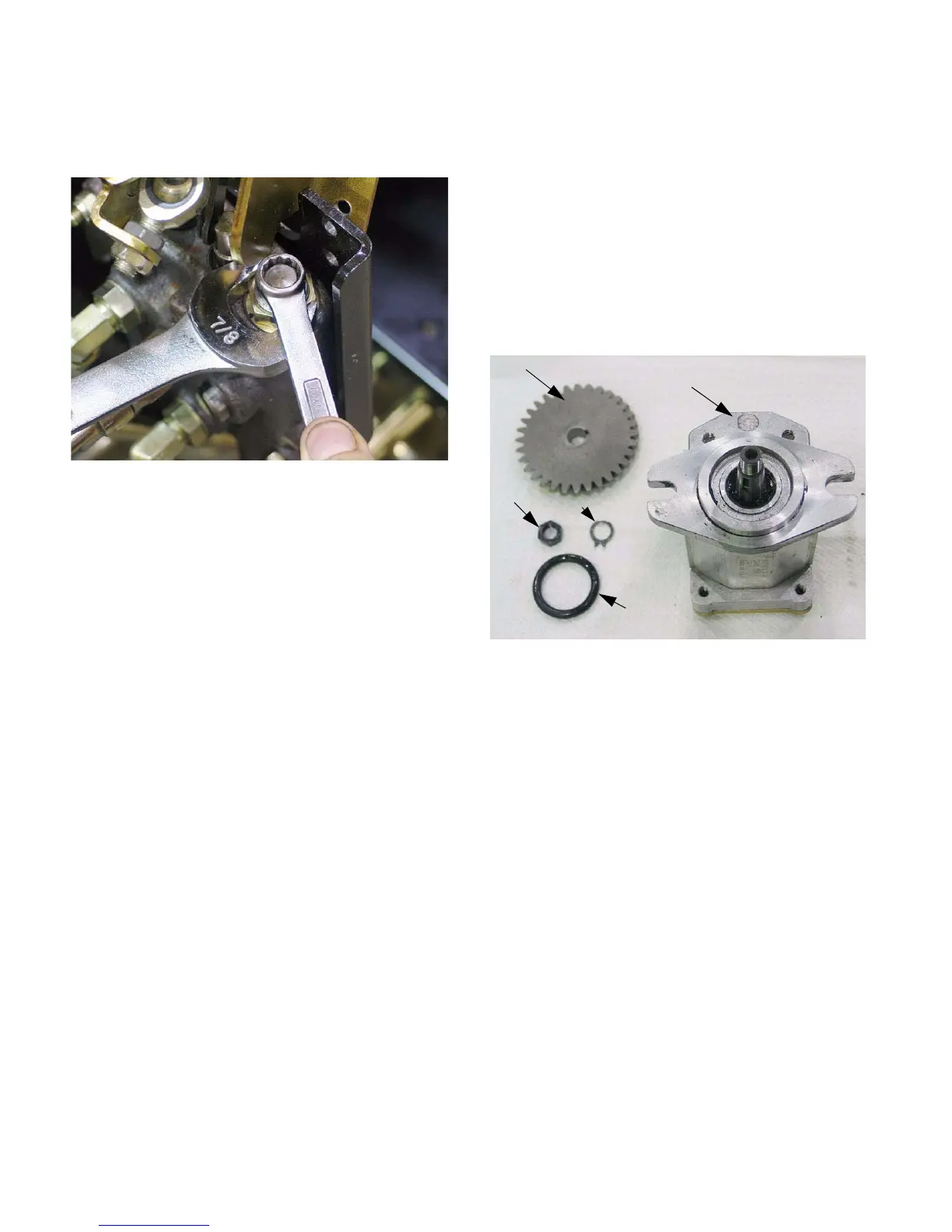
10.13.Loosen the jam nut using a 7/8” wrench and turn
the adjuster screw using a 7/16” wrench.
See Figure 10.13.
10.14.Make adjustments to the relief valve in single-
facet increments:
• Loosen the jam nut.
• Make adjustment: 1/6th turn or less.
• Tighten jam nut.
• Install pivot bracket.
• Test relief valve pressure.
• Repeat as necessary.
•DO NOT “crank-up” the pressure beyond 1,500
PSI (103 Bars).
• Install the fenders when adjustment is com-
pleted.
10.15.The pressure readings at both sets of ports
should respond equally to adjustments made to
the relief valve. If there is substantial difference
between the pressures found at the two sets of
ports, there is an internal problem with the
loader valve.
10.16.If the loader valve does not respond to adjust-
ment, or does not perform as described in this
section, replace the valve.
11. COMPONENT BREAKDOWN: AUXILIARY
PUMP (TANDEM PUMP SIMILAR)
NOTE: The auxiliary pump is to be replaced as a
unit if it fails. Dissassembling it will VOID the
warrantee. The pump has been disassembled
here to illustrate how it works.
NOTE: Individual pump components will not be
available through Cub Cadet.
11.1. The gear must be removed from the pump in
order to remove the pump from the transmission.
See Figure 11.1.
• The gear is a taper-fit to the pump shaft, and it is
keyed to the shaft.
• The lock tab, key, and nut are included with the
pump.
• The nut and shaft have a non-standard metric
thread. They will not be commonly available.
• An O-ring seal and Ultra-black sealant are used
to seal the pump to the front of the transmission.
Figure 10.13
Figure 11.1
Auxiliary pump drive gear
Nut
Lock tab
O-ring seal
Auxiliary pump

 Loading...