Domestic Series 7000 Hydraulics
27
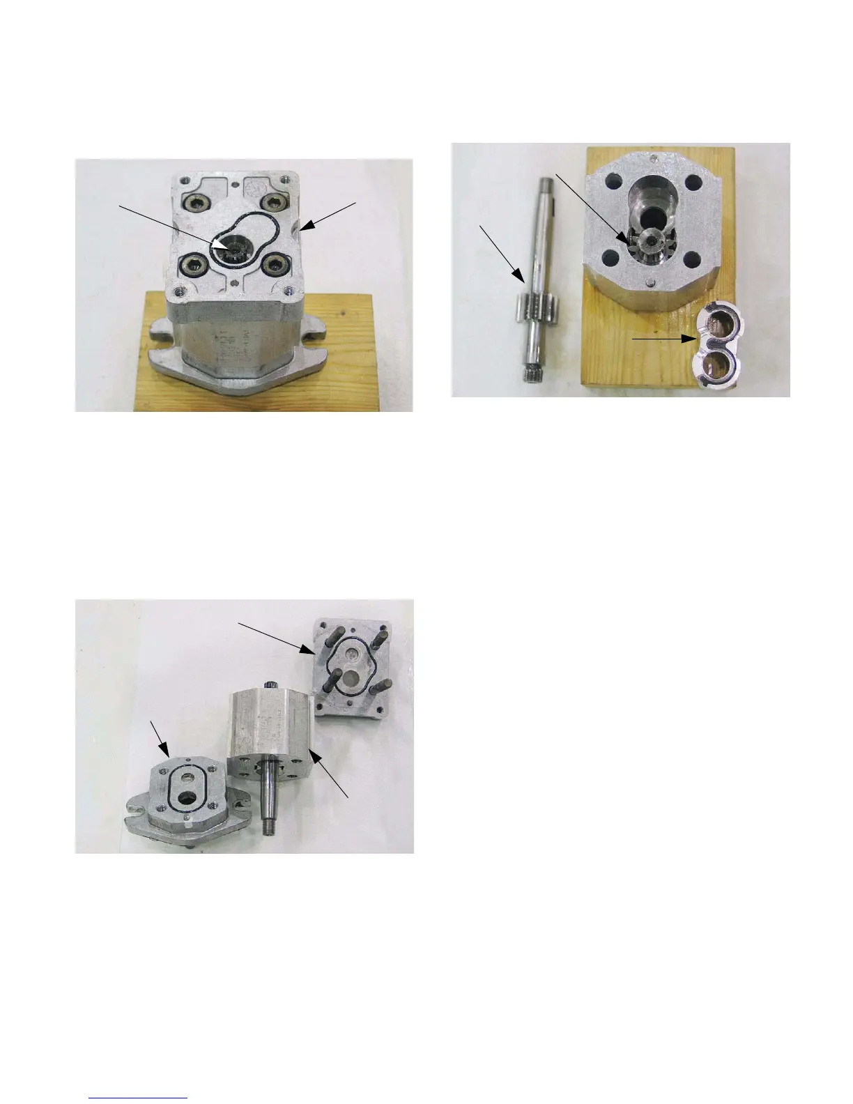
11.2. The back cover can be removed from the pump
by removing the four socket head cap screws.
See Figure 11.2.
11.3. Removing the rear cover reveals an O-ring seal,
the splined shaft that transmits power to the tan-
dem pump (when fitted), and four more socket
head cap screws.
11.4. The second set of socket head cap screws holds
the two housing ends to the body of the pump.
See Figure 11.4.
11.5. Both ends of the pump have O-ring type seals
where they meet the pump body.
11.6. The body contains a simple gear pump.
Figure 11.2
Pump with back
cover removed
Splined shaft
Figure 11.4
Pump body
Housing end: back
Housing end:
mounting
11.7. There is a cartridge that slides into the pump
body. See Figure 11.7.
• The gears operate within, and are located by the
cartridge.
• The cartridge end is partially sealed. Lubrication
channels direct a metered amount of pressur-
ized oil to the bearings and thrust surfaces.
Figure 11.7
Shaft with
pump gear
Second
pump gear
Bearing
cartridge

 Loading...