Domestic Series 7000 Hydraulics
4
1.19. If the fluid is required by the lift cylinder, it will go
to the bottom port of the lift valve instead of the
return manifold.
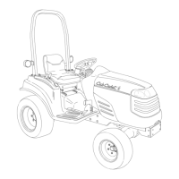
1.20. The lift valve sends fluid to the single-acting lift
cylinder when operator demand and the feed-
back rod direct it to do so. See Figure 1.20.
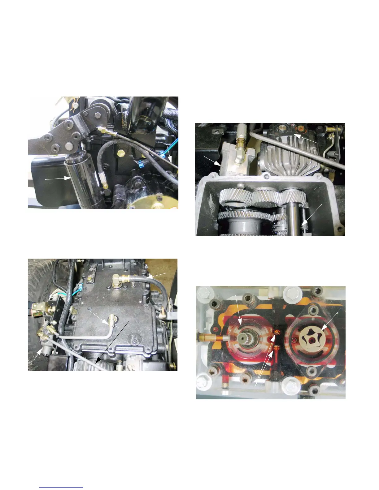
1.21. Fluid not required to lift the cylinder will be
directed back to the transmission through the
return manifold, via the cooler. See Figure 1.21.
1.22. Excess fluid volume beyond normal return flow
rate is generated when the lift arms are lowered.
This flow is exhausted directly back into the
transmission housing.
2. HYDROSTATIC DRIVE: BASIC OPERATION
2.1. The input shaft to the D15U turns a shaft that
passes completely through the housing of the
hydro., driving an engine speed input shaft in the
transmission.
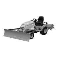
2.2. The input shaft drives the auxiliary hydraulic
pump and the P.T.O. They are driven at rela-
tively constant engine speed, rather than in rela-
tion to ground speed. See Figure 2.2.
2.3. The input shaft also turns a gerotor style charge
pump and an axial piston variable displacement
hydraulic pump. See Figure 2.3.
NOTE: Figure 2.3 is a similar model hydrostatic
drive unit with some see-through components.
Figure 1.20
Lift
cylinder
rod
Feedback
Figure 1.21
Line from return
manifold and oil cooler
Lift valve
Direct return line from
lift cylinder (when lowered)
To return
manifold
Figure 2.2
Auxiliary
hydraulic
pump
Input
shaft
for PTO
Hydro.
Figure 2.3
Charg
pump
Charge check valves
Fixed displacement
motor
 Loading...