Domestic Compact Dash and Steering Pump
68
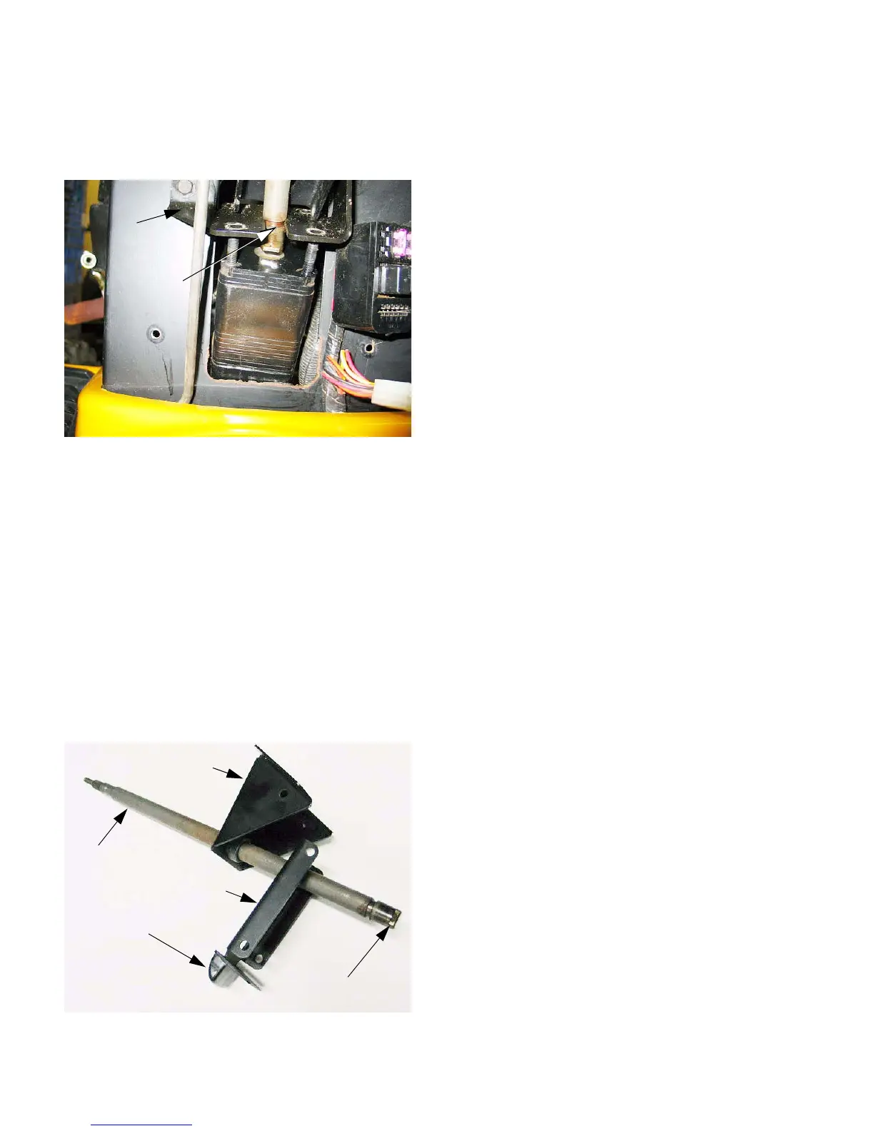
4.7. After the lines are disconnected, and the lines
and fittings are capped, remove the nuts that
secure the steering pump to the pump mounting
bracket using a 1/2 wrench.
4.8. As the pump is lowered away from the bracket, it
will separate from the steering shaft.
• The steering shaft has a “Double-D” section at
the end of the shaft that engages the pump.
• A groove in the steering shaft engages the pump
bracket. The steering shaft cannot be removed
until the pump is lowered.
4.9. Once the pump is separated from the shaft, the
pump can be removed from the tractor.
4.10. The steering shaft can be lifted out of the tractor
along with the steering coumn bracket. See Fig-
ure 4.10.
4.11. At the technician’s discretion, the retaining ring
securing the steering shaft to the steering col-
umn bracket can be removed, and the two parts
separated before this stage, but it is not essen-
tial to removing the steering pump or shaft.
4.12. Intallation is the reversal of the removal process.
The following are notes on installation:
• Position the steering shaft and steering coulmn
bracket as an assembly.
• Attach the steering pump to the pump mounting
bracket, connecting the parking brake lever and
parking brake rod in the process . It will be nec-
cesssary to rotate the steering shaft until the
base of the shaft engages the steeering pump
before the nuts that secure the pump can be
tightened.
• If the nylon locking feature of the nuts has worn-
out, replace them with new nuts or apply a small
amount of threadlocking compound such as Loc-
tite 242 (blue) to the threads. Tighten the nuts to
a torque of 17 ft.-lbs.
• Bolt the steering column bracket to the pedestal.
• Connect all of the hydraulic fittings previously
removed from the the pump.
• Install the dash panel and steering wheel on the
tractor, but do not fasten the dash panel in place.
• Connect the main wire harness to the dash
panel wire harness and the instrument panel.
• Test run the tractor in a safe area to check the
operation of the steering and to confirm that
there are no hydraulic leaks. Repair any prob-
lems that are identified.
• After successful testing, complete final assem-
bly.
Figure 4.7
Pump
bracket
mounting
Groove in
steering
shaft
Figure 4.10
Steering shaft
Double D end
Brake lever bracket
Brake lever
Steering column
bracket

 Loading...