26 se c t i O n 6— Ma i n t e n a n c e & ad j u s t M e n t s
Adjustments
WARNING!
ignition key and engage the parking brake before
heavy gloves when handling the blades.
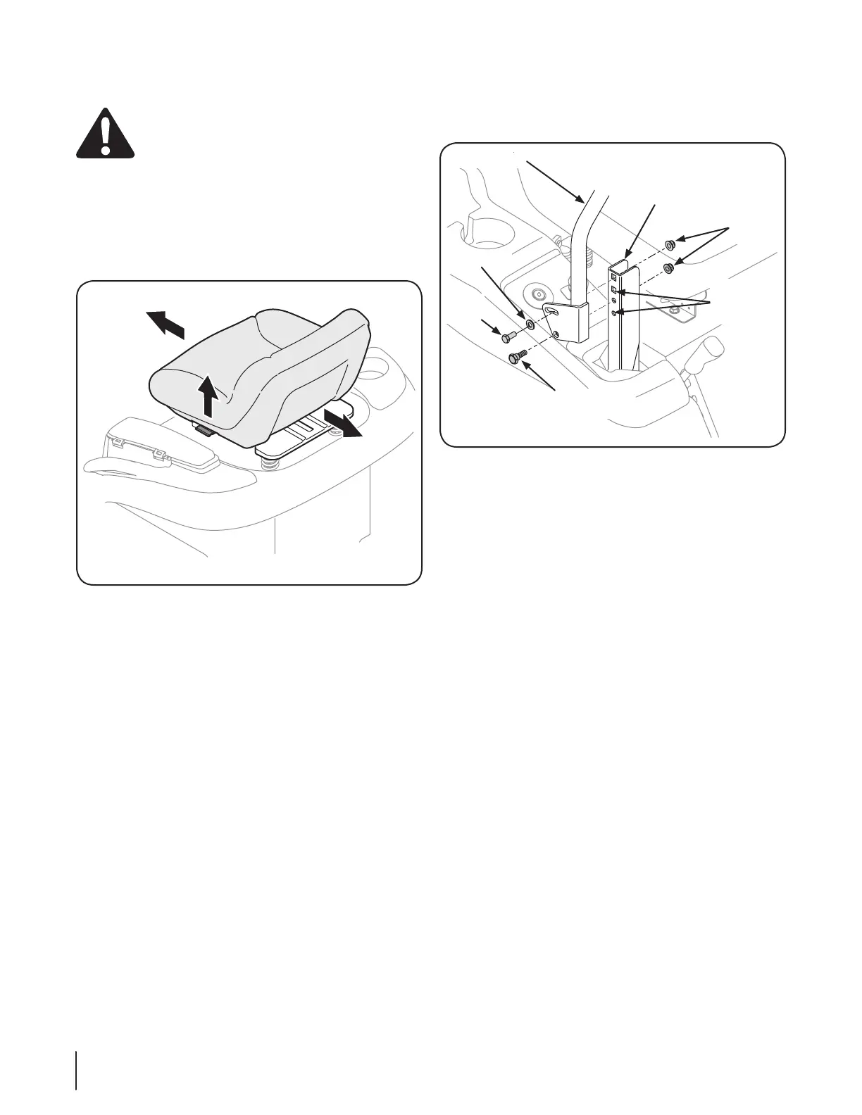
Adjusting the Seat
To adjust the position of the seat, pull up and hold the seat
desired position; then release the adjustment lever. Make sure
6-4.
Adjusting RH & LH Drive Control Levers
and fore-and-aft for the comfort of the operator. The drive
control levers can be placed in either of two height positions,
and/or can be moved forward or rearward within the range of
the slot in each control lever mounting bracket.
To adjust the drive control lever height, proceed as follows:
Remove the flange lock nut, flat washer, and hex screw securing
the lever to the pivot bracket.
While supporting the control lever to keep it from falling, 2.
remove the hex insert flange lock nut and shoulder screw
from the bottom of the control lever and pivot bracket.
Refer to Fig. 6-5.
Reposition the control lever to align with the other set of
holes in the pivot bracket and insert the shoulder screw
removed earlier. Fasten with the hex insert flange lock nut
and tighten until snug.
Insert the hex screw with washer through the control lever slot 4.
and the pivot bracket. Thread the flange lock nut onto the
screw, but do not tighten now.
If you are going to adjust the control levers forward or rearward, 5.
proceed to the next step. If not, fully tighten the flange lock
nut.
To adjust the drive control levers forward or rearward, proceed as
follows:
If not already loose, loosen the flange lock nut and rotate
the control lever either forward or rearward to the desired
NOTE: If the control lever is too tight to move, slightly
loosen the hex insert flange lock nut and shoulder screw at
the bottom of the control lever.
Tighten the flange lock nut to fix the control lever in the adjusted 2.
position
Repeat the above procedure to adjust the other control lever into
the same position. Adjust so that both levers are even with
each other when in the neutral position.
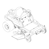
Figure 6-4
Control Lever
Pivot Bracket
Flange
Lock Nut
Height
Adjustment
Holes
Shoulder
Screw
Flat Washer
Hex
Screw
Figure 6-5
 Loading...