Maintenance 49
Cat. No. 01023552
Circuit Board
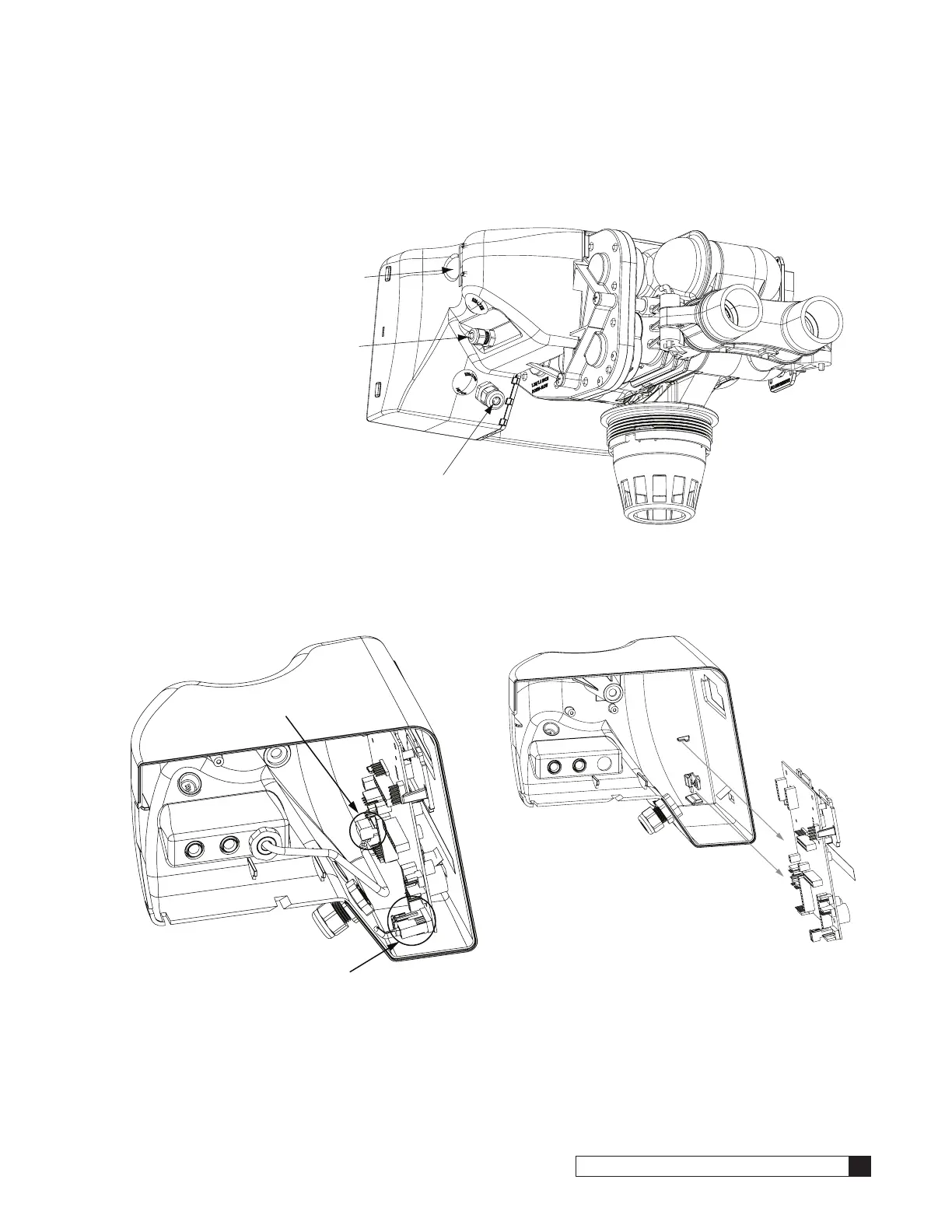
1. Remove the electrical enclosure from the control valve. Remove the electrical enclosure screw, and then gently
remove the enclosure from the control. See Figure 57.
Figure 57. Electrical and accessory connections.
2. Remove the 24V power supply wire harness and flow meter connectors from the circuit board. See Figure 58.
3. Grip the circuit board from the edges and gently rotate it to the back of the enclosure (disengage the circuit
board from the two support pins on the bottom of the enclosure). See Figure 59.
Disconnect Flow Meter
Disconnect 24V Power
Figure 58. Remove flow meter and 24V connections.
Figure 59. Remove circuit board.
4. Remove the circuit board from the enclosure.
5. Remove all connected wires from the board.
6. To install a new circuit board, follow steps 1–5 in reverse order.
7. Reprogram the circuit board.
24V Power Cord (also 2.5VAC
for optional Aqua-Sensor)
Flow Meter Wire Harness
Electrical Enclosure Screw
 Loading...