M1 RO Parts Diagrams and Lists 47
Cat. No. 01022940
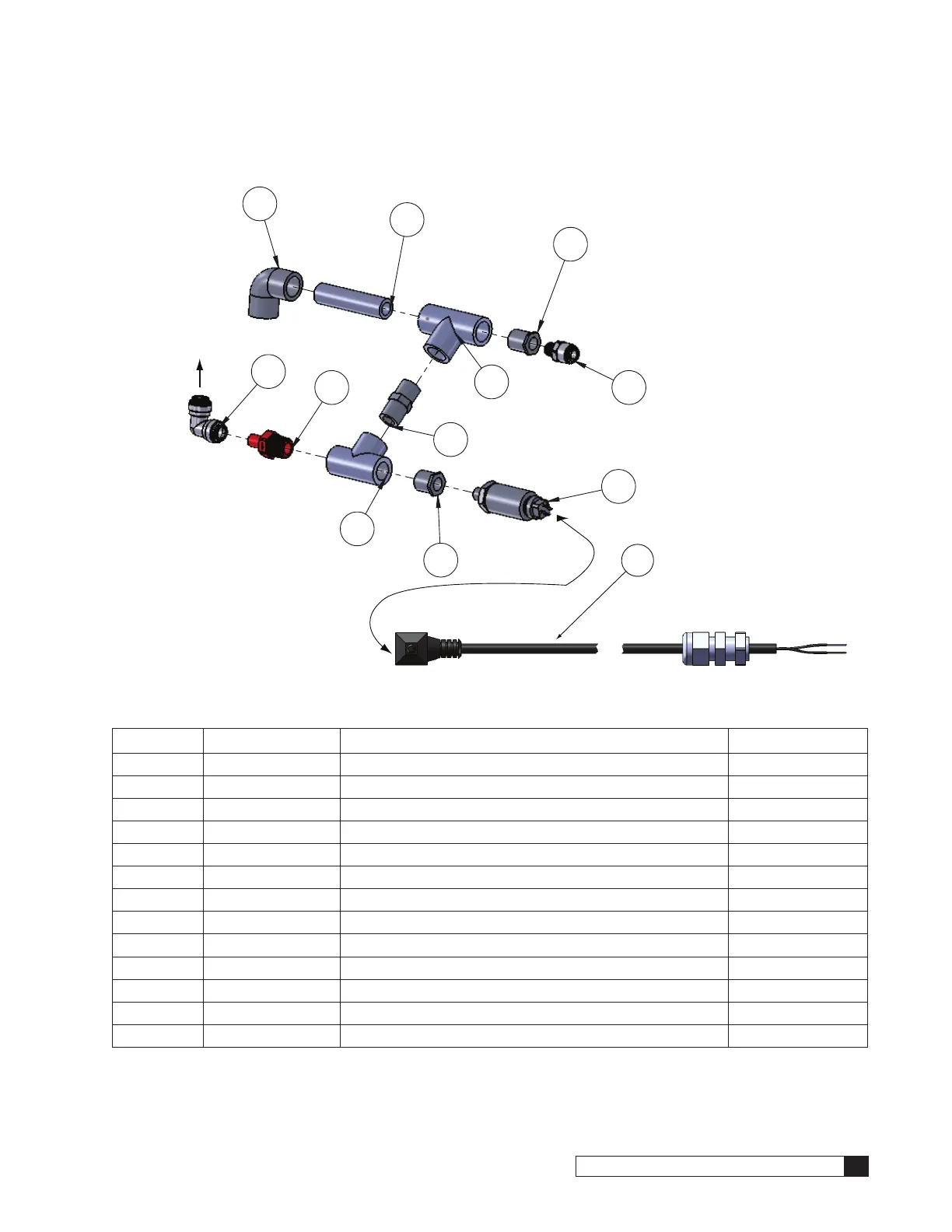
Return/Recycle Assembly and Pressure Transducer
10
1
2
7
6
5
3
4
8
9
11
To Pump Inlet
12
Figure 29. Return/Recycle assembly with pressure transducer.
Item Part No. Description Quantity
01021993 Assembly, Return (items 1–11)
1 — 1/2" Sch.80 Pipe, 3.5" length 1
2 — Tee, 1/2” Socket, PVC Sch.80 1
3 — Tee, 1/2", Threaded, PVC Sch.80 1
4 — Male Adapter, 1/2" Spigot x NPT, Sch.80 1
5 — Bushing, 1/2"x1/4", TxT, PVC Sch.80 1
6 01024302 Switch, Adjustable Pressure, 6–30 PSI 1
7 — Bushing, 1/2”x1/4”, SxT, PVC Sch.80 1
8 — Stem Adapter, 1/2T x 1/2 Stem, Polypropylene 1
9 — Elbow, Union, 1/2 Tube, Polypropylene 1
10 — Elbow, 1/2” Soc, Sch.80 1
11 — Connector, Male, 1/4 NPT x 3/8 Tube, PI, Polypropylene 1
12 01022370 Cable, Pressure, Transducer, 39"L 1

 Loading...


