Placement
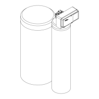
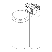
Set the media tank on a solid, level surface near water, drain and electrical
facilities. Place the outlet (black coupling) of the tank on the left. Refer to figure 2.
Install Decals
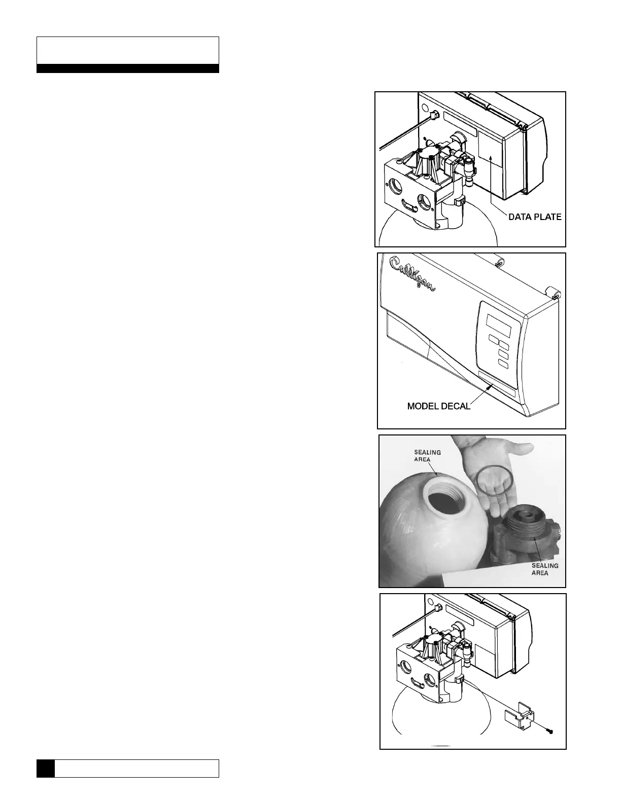
Locate the data plate decals and model decals packed with the control valve.
Adhere them to the cover and backplate as shown in figures 4 and 5.
Mount the Control Valve - 3/4” Controls
Assemble the control valve to the media tank as follows, See figure 6
1. Lubricate the O-ring sealing area of the adapter and of the tank with silicone
grease.
NOTE: Do not use a petroleum base lubricant, for this will cause swelling of
the rubber parts.
2. Remove the large O-ring from the parts pack (located in the tank adapter
carton) and assemble the O-ring onto the adapter. Be sure that the O-ring is
fully seated against the flat undersurface of the adapter.
3. Lubricate the large O-ring and the outlet manifold O-ring with silicone grease.
4. Thread the valve adapter into the tank, making certain that the outlet manifold
fits securely into the manifold O-ring. A strong hand-tight assembly is
sufficient to provide a leak-free seal.
5. NOTE: The black molded tank adapter is marked with “IN” and “OUT”,
corresponding to the inlet and outlet of the tank. Position the tank with the inlet
coupling on the right and the outlet coupling on the left. Lubricate the two O-
rings of the tank couplings with silicone lubricant.
6. The control valve is marked also with “IN” and “OUT”. Place the control onto
the tank with the inlet and outlet of the control corresponding with the inlet and
outlet of the tank. Press firmly onto the couplings.
7. Locate the two U-clamps and screws in the small parts package. Install the
clamps on both sides of the control as indicated in figure 7 and secure them
with the screws.
Figure 4
Figure 5
Figure 6
Figure 7
Installation
9 Culligan Medallist Series
®
Water Filters
 Loading...