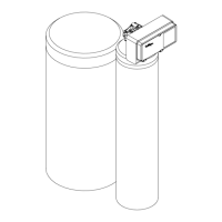
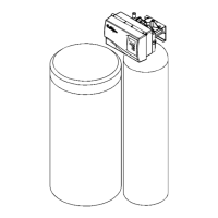
Drain Line Connection
Refer to Figure 12 and Table 2, under the applicable tank size for drain line length and height limitations.
• Remove 1/2” pipe clamp from end of drain elbow.
• Route a length of 1/2” drain line from the drain elbow to the drain.
• Fasten the drain line to the elbow with the clamp.
• Secure the drain line to the drain to prevent its movement during regeneration. A loop in the end of the tube will keep it filled
with water and will reduce splashing at the beginning of each regeneration.
Average
Water
Pressure
psi
Height of Drain Discharge Above Floor on Which Filter Sets
4” 1 ft. 2 ft. 3 ft. 4 ft. 5 ft. 6 ft. 7 ft. 8 ft. 9 ft. 10 ft.
30 56 50 40 30 20 10
50 112 106 96 86 76 66 56 46 36 26 16
70 143 137 127 117 107 97 87 77 67 57 47
90 153 147 137 127 117 107 97 87 77 67 57
120 159 153 143 133 123 113 103 93 83 73 63
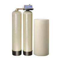
Table 2 - Culligan
®
Automatic Water Filters, 8 Inch
Average
Water
Pressure
psi
Height of Drain Discharge Above Floor on Which Filter Sets
4” 1 ft. 2 ft. 3 ft. 4 ft. 5 ft. 6 ft. 7 ft. 8 ft. 9 ft. 10 ft.
30 44 38 28 18
50 103 97 87 77 67 57 47 37 27 17 7
70 129 123 113 103 93 83 73 63 53 43 33
90 145 139 129 119 109 99 89 79 69 59 49
120 153 147 137 127 117 107 97 87 77 67 57
Table 3 - Culligan
®
Automatic Water Filters, 10 Inch
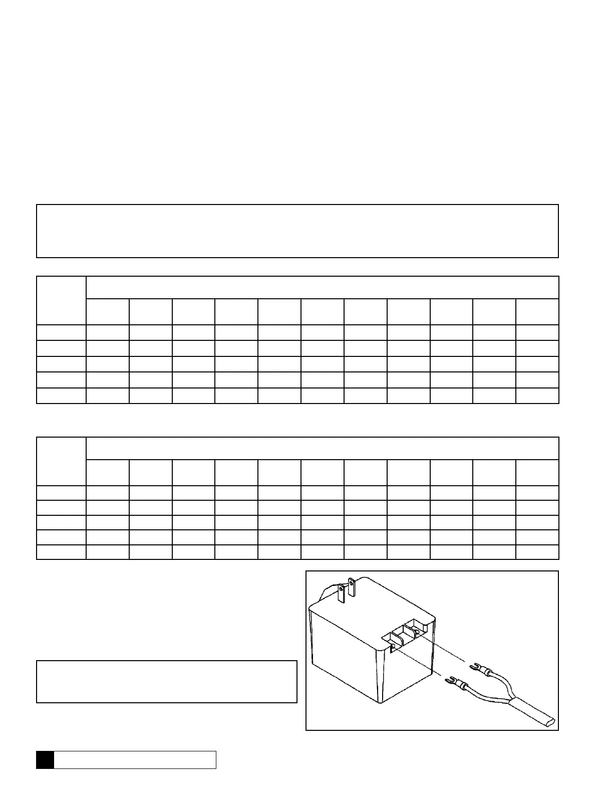
Electrical Connections
The power cord needs to be connected to the plug-in transformer,
wire orientation is not critical. Figure 15 shows the cord
attachment to the transformer.
Figure 15
Note: Waste connections or drain outlets shall be designed and constructed to provide for connection to the sanitary waste
system through an air gap of 2 pipe diameters or 1 inch, whichever is larger.
Note: Observe all plumbing codes. Most codes require an anti-siphon device or air gap at the discharge point. The system and
installation must comply with state and local laws and regulations.
13 Culligan Medallist Series
®
Water Filters
Note: Observe all state and local electrical codes.
Note: The plug-in transformer is rated for indoor installations
only.
 Loading...