DKC600(U) & DKC600 (U)Y SLIDING GATE OPERATOR USER’S MANUAL
3. Main Features
The device is used to drive sliding gate.
For your safety, the gate operator will stop and reverse if it was obstructed on closing
and stop when it was obstructed on opening.
User programmable and user erasable remote codes.
Infrared terminal (N.C) is supplied to use.
Manual key release design for emergency purposes.
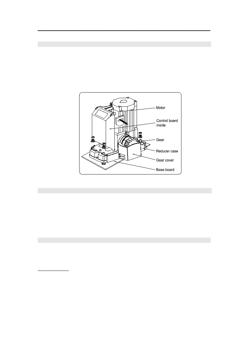
Fig.1
4. Working Principle and Main Structure
DKC600(U)Y all-in-one multifunctional sliding gate operator integrated the electric control
board into the operator, it is composed of a single-phase motor, worm and worm gear, the main
shaft of the motor rotates the worm with the clutch engaged, the worm rotates the worm gear
and output gear, which pushes the rack attached to the sliding gate, thus moving the gate.
Control board not included in DKC600 (U) main unit, it can be fitted with the KZB14-2.
5. Installation and Adjustment
The DKC600(U) & DKC600(U)Y rack-driven gate operator operates by forcing a drive rack past
a drive gear. The entire configuration is shown in Fig.2 or Fig.3. The gate operator must be
installed on the inside of the gate.
Gate preparation
Be sure the gate is properly installed and slides smoothly before installing the sliding gate
operator. The gate must be plumb, level, and move freely.