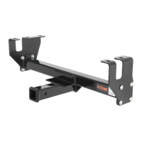
Parts List
DESCRIPTIONPART NUMBERQTYITEM
CARRIAGE BOLT7/16-14 x 181
CARRIAGE BOLT7/16-14 x 1 1/412
.250 x .88 x 2.25" SQUARE HOLE SPACERCM-SP213
HEX FLANGE NUT7/16-1494
7/16" FISHWIRE7_16 FISHWIRE15
3
2
1
5
4
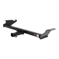
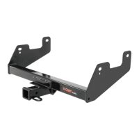
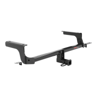
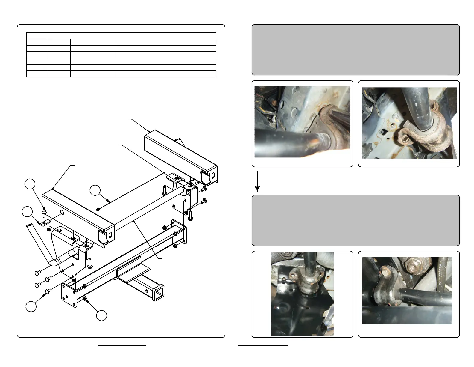
1. Remove front stabilizer bar bushing retaining bolts (save
bolts for reinstallation)
2. Slide drivers side plate into place, inbetween frame and
bushing retaining bracket. Reinstall the 12mm bolts.
Leave hardware loose until all bolts are installed.
DRIVER SIDE
FRAME RAIL
PASSENGER SIDE
FRAME RAIL
VEHICLE
STABILIZER
BAR
BUSHING RETAINER
BRACKET
 Loading...