CURTMFG.COM
•
PRODUCT SUPPORT: 877.287.8634
•
52042-INS-RE
•
01/25/2023
•
ECN10481
•
PAGE 2
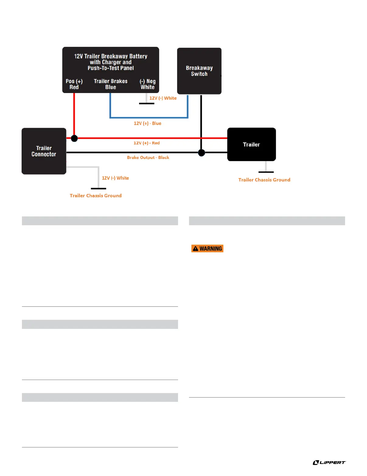
WIRING DIAGRAM
Step 2 - Wiring Breakaway Switch
Ensure the breakaway switch pin is fully installed.
Splice the blue wire from the breakaway switch to the
blue trailer brake wire from the breakaway battery box.
Splice the black wire from the breakaway switch
into the Trailer 7-way connector brake circuit.
The color of the brake circuit may vary trailer to trailer.
Step 1 - Mounting
Position the breakaway switch on the tongue of the trailer so that it
allows the cable to reach the tow vehicle's trailer hitch safety chain
eyelets. This is critical for proper engagement of switch.
Identify a suitable mounting location and drill a 9/32" hole
in the trailer frame to mount the breakaway switch. Use the
provided hardware to mount the switch to the trailer Note: Use
caution when drilling the hole, making sure there are no wires
or other objects behind the drilling surface. Do not to
over-tighten the bolt so the breakaway switch can pivot.
Find a suitable location on the trailer frame to mount the battery case.
Mount in a location that it does not interfere with the switch's lanyard.
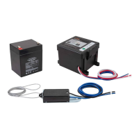
Step 3 - Wiring Breakaway Battery Box
Splice the red battery positive wire from the breakaway battery box
to the Trailer 7-way connector 12V+ auxiliary power circuit. The color
of the 12V+ auxiliary power circuit may vary from trailer to trailer.
Attach the white wire from the breakaway battery box
to the trailer chassis using a ring terminal. Be sure the
attachment point is tight, clean and free of paint and rust.
Step 4 - Post-Installation Test
After the full installation of the breakaway kit following
steps 1 through 3, it is important to test the system.
Do not perform this test with the trailer’s
7-way connector connected to a tow vehicle.
Safely lift the trailer off the ground using a jack and jack stands
so that the wheels are can free spin without touching the ground.
Spin a trailer wheel and pull the pin on the breakaway switch.
The wheel should immediately stop spinning simulating
trailer brake application during a trailer breakaway situation.
Verify the brakes are applied by attempting to
rotate the wheels. Leave the breakaway pin pulled
with the trailer brakes applied for 15 minutes.
After 15 minutes, again attempt to rotate
the wheels. The trailer brakes should still be
applied and the wheels should not be able to spin.
Reinsert the breakaway switch pin.
Safely lower the trailer back to the ground.
After performing the post-installation test, the
breakaway battery will need to be recharged before
first use. See the Battery Charging and Maintaining section.
 Loading...