6 — COMMISSIONING
Curtis AC F4-A Motor Controller – August 2020 Return to TOC
pg. 138
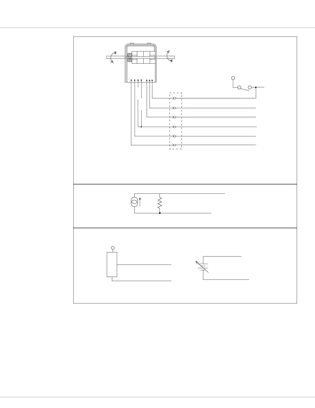
ORANGE
WHT/BRN
BLACK
BLACK/WHITE
WHITE
GREEN
B+
KEYSWITCH
WHT/GRN
Reverse (KSI Volts output)
KSI
Throttle ( 0-5 V Output)*
Forward (KSI Volts output)
I/O Ground (Bat -)
Battery + ... after KSI(2)
I/O Gnd (Pot Low)
(1)
(3)
(4)
(7)
(8)
ET-126 Throttle connector <_ _ _
AMP Mate-N-Lok
Plug p/n: AMP 350720-1
With pins: 350561-1 (strip form)
350690-1 (loose piece)
_ _ _>
AMP Mate-N-Lok
Cap p/n: AMP 350782-1
With sockets: 350851-1 (strip form)
350689-1 (loose piece)
brass, pre-tin
contacts
Forward
Reverse
* 0-5V output in each direction, Forward and Reverse
Curtis ET-xxx Hall-effect Wigwag Throttle
+
+
-
SENSOR OUTPUT (0–5V)
S E NSOR
SENSOR GROUND
I/O Ground Return (Pin 7)
Pot 1 Wiper input (Pin 16)
Sensor-reference 0-5V source Ground-reference 0-5V source
Pot 1 Wiper input (Pin 16)
I/O Ground Return
(Pin 7)
Voltage Source
Pot 1 Wiper input
(Pin 16)
I/O Ground Return (Pin 7)
R
throttle
I
source
Current Source
Figure 28
Wiring for Voltage type
throttles
Other throttle parameters
Complete the throttle setup by adjusting the remaining parameters to match the range of the throttle,
else tune these parameters when operating the motor following this initial setup. See the Programmer
» Application Setup » rottle menu.
Forward Min Input,
Forward Max Input,
Forward Map Shape,
Quick Link:
rottle menu p.48