EasyManuals Logo

Curtis 1268-5403 User Manual

Curtis 1268-5403
6 pages
To Next Page IconTo Next Page
To Previous Page IconTo Previous Page
Page #2 background imageLoading...
Page #2 background image
Generic Golf (1268-5403) Install Sheet-370 Rev 01 05/25/18 Sheet 2 of 6
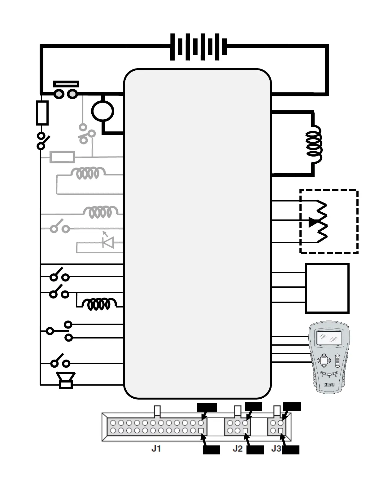
Brake Light
Relay
Diagram shows the
back (wire) side of
controller connector
1268-5403
Controller
Run/Tow
Switch
J1-10 (Forward In)
J1-11 (Reverse In)
Reverse Alarm
J1-19 (Backup Alarm Out)
Pedal Switch
Speed
Sensor
Out
+
-
(Speed Sensor Supply) J2-6
36V/48V Battery Pack
+
-
F1
B-
B+
A
Main Solenoid
Contacts
A1
M-
A2
Motor
Armature
F1
Motor
Field
F2
F2
Walkaway Relay
J1-23 (Walkaway Driver) [Opt.]
J1-8 (Pedal Switch In)
(Speed Sensor Signal) J2-5
(Speed Sensor Ground) J2-4
FUSE
J1-3 (Walkaway Fuse Sense) [Opt.]
FUSE
J1-20 (Mode Switch In) [Opt.]
Mode
Switch
J1-9 (Walkaway Return) [Opt.]
J1-18 (Brake Light Relay) [Opt.]
J1-4 (Logic Power In)
J1-2 (Logic Enable In)
Charger
Interlock
J1-1 (Key Switch In)
Key Switch
J1-17 (Main Contactor Out)
Main Contactor
J1-22 (LED Driver) [Opt.]
J1-16 (LED Ground) [Opt.]
Throttle
Pot
(Pot High) J1-13
(Pot Wiper) J1-15
(Pot Low) J1-14
(RX Data) J3-1
(B-) J3-2
(TX Data) J3-3
(+15V) J3-4
Pin 1
Pin 13
Pin 4
Pin 3
Pin 1
Pin 1

Questions and Answers:

Question and Answer IconNeed help?

Do you have a question about the Curtis 1268-5403 and is the answer not in the manual?

Curtis 1268-5403 Specifications

General IconGeneral
BrandCurtis
Model1268-5403
CategoryController
LanguageEnglish

Related product manuals