Curtis 1214-/15-/19-8 Manual
APPENDIX A: FEATURES & FUNCTIONS
A-8
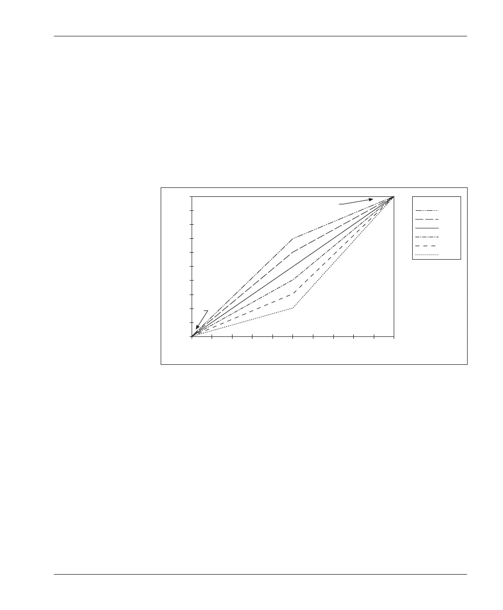
Ramp shape (throttle map)
“Ramp shape” is a programmable parameter that determines the static throttle
map of the 1214-/15-/19-8 controller. Eleven preprogrammed ramp shapes are
available, in 5% steps between 20% and 70% (20, 25, 30, 35, 40, 45, 50, 55, 60,
65, and 70%). The ramp shape number refers to the PWM output at half
throttle, as a percentage of its full range. For example, if maximum speed is set at
100% and creep speed is set at 0, a ramp shape of 50% will give 50% output at
half throttle. The 50% ramp shape corresponds to a linear response. The six “even
number” ramp shapes for maximum and creep speeds set at 100% and 0 are
shown in Figure A-1.
Changing either the maximum speed setting or the creep speed setting changes
the output range of the controller. Ramp shape output is always a percentage of
that range. Ramp shapes with the creep speed setting raised to 10% are shown in
Figure A-2. In Figure A-3, the creep speed is kept at 10% and the maximum
speed setting dropped to 60%.
THROTTLE (percent)
PWM (percent)
70%
60%
50%
40%
30%
20%
RAMP SHAPE
100
90
80
70
60
50
40
30
20
10
0
100908070605040302010 0
CREEP
SPEED
(0)
MAXIMUM SPEED (100%)
Fig. A-1 Ramp shape
(throttle map) for control-
ler with maximum speed
set at 100% and creep
speed set at 0.